Frequency Counter Schematic using Microcontroller AT89C51 is a simple yet mostly used frequency counter schematic used. The reason behind its simplicity also lies somewhere in the fact that this project uses only two components-AT89C2051 microcontrollers and a 16*2 LCD.
Frequency is a crucial subject matter in every project. Precise and accurate frequency generation is another challenge we face in varieties of project design. As per the design of this project, this circuit can withstand frequency ranges between 1 Hz to ~16.5 Mhz, and the rest depends on the characteristics of the pin.
Working Principle and Circuit Description of Frequency Counter Schematic
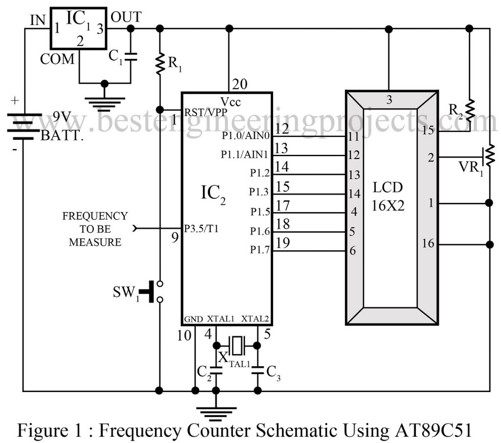
The circuit diagram of the frequency counter schematic using microcontroller AT89C51 is shown in figure 1. What is the frequency? It is the number of cycles per second made by the signal. This is the core principle used in every frequency measuring project and we did the same. The 8051 microcontroller comes equipped with two inbuilt timers- timer 0 and timer 1, both of which are configured to be used for different purposes.
The first-timer 0 is employed to sample the input signal and is fixed at a single-second delay. Talking about the other one; timer 1, represents a counter that keeps a record of several cycles covered in a single-second delay. Considering the case of overflow, another register is assigned to handle that situation. The overflow register is also termed as a high byte of frequency since it holds a higher value of frequency.

Pin P3.5/T1 (pin 9) which is timer 1 external input pin of the microcontroller, fetches the input signal as it is applied at that port. Port 1 of the microcontroller is used to interface LCD in the 4-bit mode for this project. Here we have used a 2-line LCD. However, this project can also be used along with a single line LCD with proper configuration.
On the course of programming, timer 0 is initialized in 16-bit mode with a 50 mS delay value. A tick value of 20 is programmed to be equal to a total delay of 1s (50 x 20 = 1000 mS). Timer 1 in counter mode is programmed in 16-bit mode. During the first 1 second delay, a sample of the input signal is extracted and timer 1 calculates the number of cycles and hence the frequency of the input signal is determined and a high byte of frequency is recorded. Frequency is stored as TH1:TL1. In total 3 bytes value is obtained which is then converted into a decimal equivalent represented in hex. This result is displayed on LCD and the same process repeats again and again unless the signal is sampled completely and frequency is calculated.
Check out other interesting projects using AT89C51 posted in bestengineeringprojects.com
- DIY Soccer Substitution Board using AT89C51
- Microcontroller AT89C51 based Metro Train Prototype
- AC Motor Speed Controller Circuit Using AT89C51
- Monitoring System using AT89C51
PCB Diagram of Frequency Counter Schematic
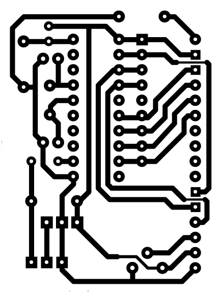
The actual size PCB diagram for circuit Frequency Counter Schematic Using Microcontroller is shown below
Figure 2: Solder Side PCB diagram
Figure 3: Component Side PCB diagram
Software: Software for frequency counter schematic using microcontroller is given here in link Click Here To Download Source Code. You can directly download and burn it into the microcontroller.
PARTS LIST OF FREQUENCY COUNTER SCHEMATIC USING MICROCONTROLLER
| Resistors (all ¼-watt, ± 5% Carbon) |
| R1 = 10 KΩ
R2 = 47 Ω VR1 = 10KΩ |
| Capacitors |
| C1 = 100 nF (Ceramic Disc)
C2, C3 = 33 pF (Ceramic Disc) |
| Semiconductors |
| IC1 = LM7805 (5V linear series voltage regulator)
IC2 = AT89C51 (Microcontroller) |
| Miscellaneous |
| LCD1 = 16X2 Alpha numeric LCD
SW1 = Push to on switch XTAL1 = 12MHz crystal oscillator 9V Battery |

