The project posted here is of Microcontroller AT89C51 based Metro Train Prototype which shows how metro train works. The project uses two motors, one is used for opening and closing the door and other is used for moving the train forward. This prototype of metro train is a good example of embedded system. Before talking about circuit description and working let clear the concept of embedded system.
Embedded System: An embedded system is an electronic or electromechanical system designed to perform a specific function and is a combination of both hardware and software. The project metro train prototype posted here it is combination of both hardware and software and designed for specified function thus it is an embedded system.
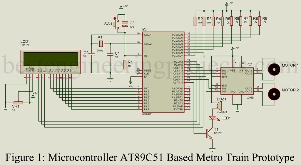
Circuit Description of Microcontroller AT89C51 based Metro Train Prototype:
The circuit of metro train prototype shown in figure 1 is designed around 8-bit microcontroller AT89C51, a motor driver IC, two DC motors and few other components in order to work flawlessly.
Here are the few reasons why we are using AT89C51 microcontroller
- Very versatile featuring powerful Boolean processor – supports bit manipulation instructions for real-time industrial control applications.
- One fascinating features – the way it handles interrupts.
- These interrupts have two priority levels and each is allocated fixed 8 bytes of code.
- Supports CAN, USB, SPI and TCP/IP interfaces, ADC/DAC, LCD controller ext. no. of I/O ports.
- Low cost.
LCD Module:
In this project, we had used 16×2 alpha numeric LCD for output which display alphabets, numbers or even other special characteristics. The LCD have two rows and each row we can display 16 characters. It can operate in either 8-bit mode or 4-bit mode, but here we are using 8-bit mode.
L293D Quadruple Half-H Driver:
This IC is high current half-H drivers which is designed to drive various kind of motors (Stepper motor, DC motor, Latching relay etc.) in bi-directional mode. This IC generates about 600-mA at voltage of 4.5V to 36V.
DC Motor:
The motor used in this prototype is DC motor type. One motor out of two is used to drive train in forward direction while other is used to control the gate (open and close).
External access pin EA (pin 31) is connected with Vcc because it is executed from internal program memory. As there no external memory, pins of port 0 must be connected externally to a 10K pull-up resistors as they are open drain. Reset pin must have the min. duration of 2 machine cycle. When power is turned on, the circuit holds the RST high for an amount of time that depends on the capacitor value and the rate at which it charges. To ensure a valid reset, the RST pin must be held high long enough to allow the oscillator to start up pulse two machine cycle. Thus, we had used 10uf capacitor with a resistor connected in series.
LCD is configured in 8-bit mode used to view the station number and station name. LCD communicate with microcontroller using port 1. Port 2 is used to control the motor driver IC which further control the two DC motors. The buzzer and LED used in this project indicate that door is close.
More other interesting project based on AT89C51 posted in bestengineeringprojects.com
- DIY Soccer Substitution Board using AT89C51
- Frequency Counter Schematic using Microcontroller AT89C51
- AC Motor Speed Controller Circuit Using AT89C51
- Monitoring System using AT89C51
Software: The software code is written in C programming and compiled using keil u version 5. The simulation of metro train is done using Proteous 8 professional. You can directly download the software from the link below. The folder contains software in c program version and HEX version.
Click here to download software
PARTS LIST OF MICROCONTROLLER AT89C51 BASED METRO TRAIN PROTOTYPE
| Resistors (all ¼-watt, ± 5% Carbon) |
| R1 = 1 KΩ
R2 – R9 = 10 KΩ VR1 = 1KΩ |
| Capacitors |
| C1, C2 = 33pF (Ceramic Capacitor)
C3 = 10 µF, 16V (Electrolytic Capacitor) |
| Semiconductors |
| IC1 = AT89C51 (Microcontroller)
IC2 = L293D (Motor Driver IC) T1 = BC107 (NPN Transistor) LED1 = 5mm any color LED |
| Miscellaneous |
| SW1 = Push-to-on switch
X1 = 12MHz crystal oscillator LCD1 = 16*2 alpha numeric LCD Motor1, Motor2 = 5V DC motor 1 Buzzer |