Quiz contests are become progressively more popular and the “buzzer” round are now an integral part of such contests. As we all know that in this round each team is provided with push-button switch and questions are addressed to each team. The team that presses the button first is allowed to answer the question.
The circuit which perform this task or which can be used for this purpose is published here “Advanced Quiz Display with Seven Segment Display”. It can accommodate up to 8 teams through switch SW1 to SW8. This circuit of advanced quiz display uses a 7-segment display to indicate the team that pressed the switch first.
Circuit Description of Advanced Quiz Display
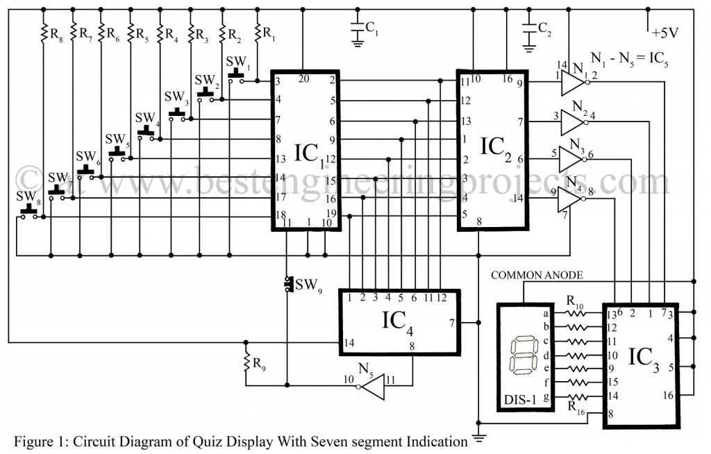
The circuit of Advanced Quiz display is based on TTL ICs,. The push-to-on switches are connected to the inputs of IC1 which is an 8-bit latch, and the output is connected to input of IC2 which is priority encoder. IC2 is used here to convert the data latched on IC1 to BCD. The output of IC2 is inverted by the inverters N1 to N4. The complemented outputs from inverters are fed to input of IC3 which is a BCD to 7-segment display decoder.
The outputs from the circuit advanced quiz display drive a common-anode, 7-segment display through current limiting resistor R10 to R16. IC4 is used to prevent the latches from registering more than one team’s input. This happen because whenever any one of the switches is pressed, the output of IC4 goes high. The complement of this input is fed to the enable input of IC1, disabling the latches until the reset switch is pressed.
The circuit of advanced quiz display with seven segment diaplay must be powered by a 5 volt power supply. The value of current limiting resistors (R10 – R16) may be increased or decreased in order to increase or decrease the brightness of display.
PARTS LIST OF ADVANCED QUIZ DISPLAY WITH SEVEN SEGMENT INDICATION
|
Resistors (all ¼-watt, ± 5% Carbon) |
|
R1 – R9 = 1.5 KΩ R10 – R16 = 560 Ω |
|
Capacitors |
|
C1, C2 = 0.1 µF (Ceramic Disc) |
|
Semiconductors |
|
IC1 = 74373 (Octal D-Type Latch) IC2 = 74147 (Priority Encoder) IC3 = 7447 (BCD TO 7-Segment Decoder) IC4 = 7430 (8-Input NAND Gate IC) IC5 = 7404 (NOT Gate IC) |
|
Miscellaneous |
|
SW1 – SW8 = Push – To – On switch SW9 = Push – To – Off switch DIS1 = LTS542 or FND507 |
“The team that presses the button first is allowed to answer the question.”
When I try this project the reset is not working. I pressed first a number, but then when I pressed a higher value number the display changed. So it’s not working. it doesn’t allow the team that press first.
What should I do?