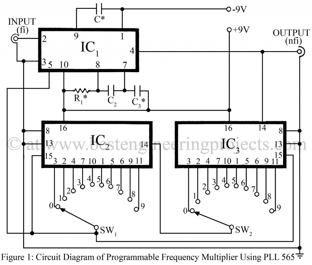
Here is a Frequency Multiplier circuit using PLL565. Phase lock loop (PLL) has many diverse applications, among its applications PLL exhibits tremendous flexibility in frequency multiplication. The IC 565 (IC1) can be used over the frequency range of 0.001 Hz to 500 kHz, and an operating voltage range of 6V to 12V. The frequency multiplier circuit has a highly stable center frequency, selected by an external resistor (R1) and Capacitor (C1), which is given by
The capture range of the feedback control system of the frequency multiplier circuit is decided by the low pass filter made up of capacitor C* and internal resistor R. The value of capacitor C* must be selected such that the cut-off frequency of the low-pass filter is above the maximum anticipated frequency difference between the input signal frequency and VCO (voltage control oscillator) running frequency.
The value of R1* must be lies between 2 KΩ and 20 KΩ.
While testing in the Dreamlover Technology lab the following values of the variable was used in the frequency multiplier circuit:
R1* = 10 KΩ
C1* = 0.002 µF
C3* = 0.001 µF
Using these values for the frequency multiplier circuit we can check the input frequencies up to 15 kHz and multiplying factor up to 33.
Frequency multiplication is achieved by breaking the feedback loop of the PLL at the VCO output and inserting a frequency divider mechanism made up of a CD4017 decade counter with one of the 10 outputs selected by the mean of the thumbwheel switch. The divided VCO output is then fed to the phase comparator. This is locked to the input frequency. Thus the VCO now runs at a multiple of the input frequency. The multiplying frequency is decided by the frequency divider and hence determined by the thumbwheel switches.
PARTS LIST OF FREQUENCY MULTIPLIER CIRCUIT USING NE565
|
Resistor (all ¼-watt, ± 5% Carbon) |
|
R1* = 10 KΩ |
|
Capacitors |
|
C1* = 0.002 µF (Ceramic Disc) C2, C3* = 0.001 µF (Ceramic Disc) |
|
Semiconductors |
|
IC1 = NE565 (Phase Lock Loop IC) IC2, IC3 = CD4017 (Decade Counter IC) |
|
Miscellaneous |
|
SW1, SW2 = single pole ten way thumbwheel switch |
