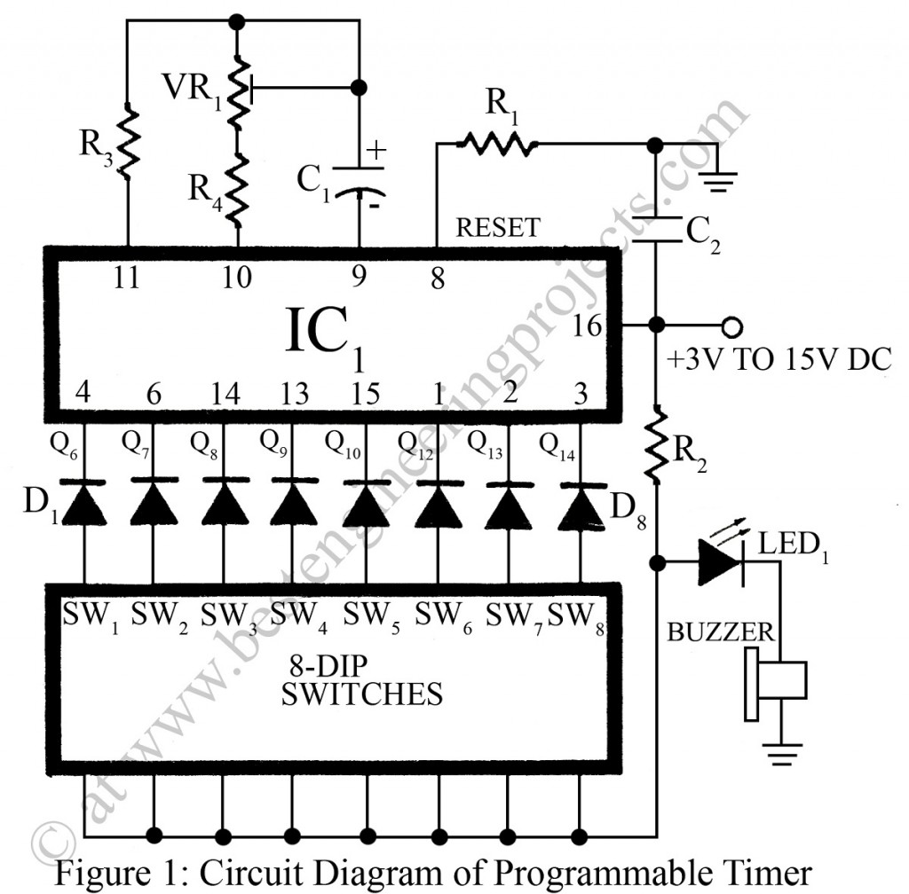
The electronic project “Programmable Timer Circuit” published here can be programmed for more than 250 different time intervals. The programmable timer circuit is not new to electronics hobbyists, various timer circuits have been designed and published so far but the circuit of the programmable timer posted here is the most versatile, inexpensive, and extremely compact timer with an alarm.
Description of Programmable Timer Circuit
The main part or heart of the programmable timer circuit is a 14-stage binary counter CD4060 (IC1). The clock pulse is generated by connecting capacitor C1, resistors R4 and R3 to terminals 9, 10, and 11 respectively of IC1 as shown in the circuit diagram. The frequency of clock pulse is adjusted by preset VR1 connected in series with resistor R4.
Power-on-reset is provided to reset the counter by giving a pulse from the supply line via capacitors C2, after which it starts counting the pulses generated by the oscillator.
Diodes D1 through D8 along with the resistor R2 are used to form an 8-input AND gate. The truth table is shown in table 1.
|
TABLE 1 |
||
|
A |
B |
Y |
|
0 0 1 1 |
0 1 0 1 |
0 0 0 1 |
The timer circuit published here has eight programmable switches, each with a fixed time interval. For example, with approximately 1.06 Hz frequency adjusted with the help of preset VR1, the output Q6 (pin 4) will go high after receiving 26 = 64 pulses, that is after about 60 seconds. In the same way, Q14 (pin 3) will go high after 214 = 16384 pulses, that is after about four-and-a-half hours.
Other interesting timer circuits posted on bestengineeringprojects.com
- Industrial Timer Circuit
- Pulse Generator Cum Timer Circuit
- Countdown Timer Using Arduino
- 24 Hour Digital Clock and Timer Circuit
- Digital Clock with Seconds and Alarm Time Display
But if Q6 and Q14 are switched on simultaneously, their time interval gets added because of the AND gate arrangement made by using the diode and the resistor. That is why 256 different time intervals can be programmed. The circuit of the programmable timer can be powered by a 9V battery.
PARTS LIST OF PROGRAMMABLE TIMER CIRCUIT
|
Resistors (all ¼-watt, ± 5% Carbon) |
|
R1 = 1 MΩ R2 = 10 KΩ R3 = 2.2 MΩ R4 = 820 Ω VR1 = 100 KΩ |
|
Capacitors |
|
C1 = 1 µF, 25V (Electrolytic Capacitor) C2 = 0.001 µF (Ceramic Disc) |
|
Semiconductors |
|
IC1 = CD4060 (14-stage binary counter) D1 – D8 = 1N4148 (silicon switching signal diode) LED1 = Red LED |
|
Miscellaneous |
|
SW1 – SW8 = 8-Dip Switch Buzzer |
