The circuit here Countdown timer using Arduino is a simple circuit with the facility of the timer, this circuit is designed for 50 minutes timer but you can change it according to your requirement. Electronic circuits are usually designed for a specific purpose, which means one circuit performs only one task, in general cases. When this circuit is used, the time at which it is selected can be stored electronically while being displayed simultaneously. Talking about the circuit components, it uses an Arduino board, 7-segment display, PNP transistor, and a few other electronic components which are commonly available.
Project Description of Countdown Timer Using Arduino
As the project countdown timer uses Arduino, it can be divided into two main parts
-
The Hardware | Countdown Timer Using Arduino
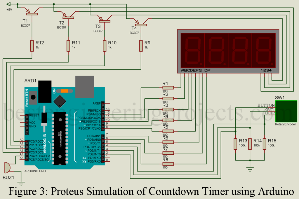
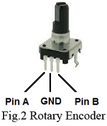
Figure 3 shows the circuit of the countdown timer using Arduino. This section includes all the hardware required. The circuit makes use of four 7-segment displays and is designed to display the time. Transistors T1 through T4 are used as a switch and always turn fully on or off. In addition, passive components like a few resistors, and switches are employed. A rotary encoder as shown in figure 2 is an electro-mechanical device that converts the angular position to an analog or digital code.
Pin of all 7-segment displays except common anode pin is connected in parallel. Eight digital pins of Arduino (D12, D11, D10, D9, D8, D7, D6, and D5) are connected to 8 pins of seven segment display (pin a, b, c, d, e, f, g, and DP) respectively. Four PNP transistor (BC307) is used to switch the display ON and OFF. +5V for Arduino UNO board is given to the emitter pin of all four transistors where the base of these transistors is connected to Arduino analog pin A0 to A3 through a current limiting resistor as shown in the circuit diagram. One piezo buzzer is connected to analog pin A4 as shown in the circuit diagram to produce audio sound. One Rotary encoder is used to select the timer and to toggle between stop and running mode. Rotary encoders have altogether 5 pin categories as output pin, button pin, and common pin. two output pin (OUT1 and OUT2) is connected to Arduino digital pin D2 and D3 respectively whereas the button pin is connected to pin D2 of Arduino. The rest of the two-pin (common pin) is connected to +5V of Arduino.
Figure 1: Author prototype of Countdown timer using Arduino
PARTS LIST OF COUNTDOWN TIMER USING ARDUINO
| Resistor (all ¼-watt, ± 5% Carbon) |
| R1 – R4 = 1 KΩ 0.5W
R5 – R7 = 100 KΩ, 0.5W R8 – R15 = 100 Ω, 0.5W |
| Semiconductors |
| Arduino Board
T1 – T4 = BC307 Dis1 – Dis4 = Common Anode 7-Segment Display |
| Miscellaneous |
| Rotary Encoder
PZ1 = Piezo Buzzer |
The Software | Countdown Timer Using Arduino
The code is so designed that all four displays are lit at the same time. There are two states in this countdown timer. In the running stage, it will countdown the timer and in the stopped state, the time will be changed by turning the rotary encoder were pressing the button on the rotary encoder will toggle between two-state. Here, we made an array of some standard times which can be changed by rotating the encoder instead of 1 second. We used the EEPROM library to store the last used time, and it always powered with the last used time
The Code | Countdown Timer Using Arduino
|
1 2 3 4 5 6 7 8 9 10 11 12 13 14 15 16 17 18 19 20 21 22 23 24 25 26 27 28 29 30 31 32 33 34 35 36 37 38 39 40 41 42 43 44 45 46 47 48 49 50 51 52 53 54 55 56 57 58 59 60 61 62 63 64 65 66 67 68 69 70 71 72 73 74 75 76 77 78 79 80 81 82 83 84 85 86 87 88 89 90 91 92 93 94 95 96 97 98 99 100 101 102 103 104 105 106 107 108 109 110 111 112 113 114 115 116 117 118 119 120 121 122 123 124 125 126 127 128 129 130 131 132 133 134 135 136 137 138 139 140 141 142 143 144 145 146 147 148 149 150 151 152 153 154 155 156 157 158 159 160 161 162 163 164 165 166 167 168 169 |
#include <EEPROM.h> int segmentPins[] = {12, 11, 10, 9, 8, 7, 6, 5}; int displayPins[] = {A0, A1, A2, A3}; int times[] = {5, 10, 15, 20, 30, 45, 100, 130, 200, 230, 300, 400, 500, 600, 700, 800, 900, 1000, 1500, 2000, 3000}; int numTimes = 19; int timerMinute; int timerSecond; int buzzerPin = A4; int aPin = 4; int bPin = 3; int buttonPin = 2; byte selectedTimeIndex; boolean stopped = true; byte digits[10][8] = { // a b c d e f g . { 1, 1, 1, 1, 1, 1, 0, 0}, // 0 { 0, 1, 1, 0, 0, 0, 0, 0}, // 1 { 1, 1, 0, 1, 1, 0, 1, 0}, // 2 { 1, 1, 1, 1, 0, 0, 1, 0}, // 3 { 0, 1, 1, 0, 0, 1, 1, 0}, // 4 { 1, 0, 1, 1, 0, 1, 1, 0}, // 5 { 1, 0, 1, 1, 1, 1, 1, 0}, // 6 { 1, 1, 1, 0, 0, 0, 0, 0}, // 7 { 1, 1, 1, 1, 1, 1, 1, 0}, // 8 { 1, 1, 1, 1, 0, 1, 1, 0} // 9 }; void setup() { for (int i=0; i < 8; i++) { pinMode(segmentPins[i], OUTPUT); } for (int i=0; i < 4; i++) { pinMode(displayPins[i], OUTPUT); } pinMode(buzzerPin, OUTPUT); pinMode(buttonPin, INPUT); pinMode(aPin, INPUT); pinMode(bPin, INPUT); selectedTimeIndex = EEPROM.read(0); timerMinute = times[selectedTimeIndex] / 100; timerSecond = times[selectedTimeIndex] % 100; } void loop() { if (digitalRead(buttonPin)) { stopped = ! stopped; digitalWrite(buzzerPin, LOW); while (digitalRead(buttonPin)) {}; EEPROM.write(0, selectedTimeIndex); } updateDisplay(); } void updateDisplay() // mmss { int minsecs = timerMinute * 100 + timerSecond; int v = minsecs; for (int i = 0; i < 4; i ++) { int digit = v % 10; setDigit(i); setSegments(digit); v = v / 10; process(); } setDigit(5); // all digits off to prevent uneven illumination } void process() { for (int i = 0; i < 100; i++) // tweak this number between flicker and blur { int change = getEncoderTurn(); if (stopped) { changeSetTime(change); } else { updateCountingTime(); } } if (timerMinute == 0 && timerSecond == 0) { digitalWrite(buzzerPin, HIGH); } } void changeSetTime(int change) { selectedTimeIndex += change; if (selectedTimeIndex < 0) { selectedTimeIndex = numTimes; } else if (selectedTimeIndex > numTimes) { selectedTimeIndex = 0; } timerMinute = times[selectedTimeIndex] / 100; timerSecond = times[selectedTimeIndex] % 100; } void updateCountingTime() { static unsigned long lastMillis; unsigned long m = millis(); if (m > (lastMillis + 1000) && (timerSecond > 0 || timerMinute > 0)) { digitalWrite(buzzerPin, HIGH); delay(10); digitalWrite(buzzerPin, LOW); if (timerSecond == 0) { timerSecond = 59; timerMinute --; } else { timerSecond --; } lastMillis = m; } } void setDigit(int digit) { for (int i = 0; i < 4; i++) { digitalWrite(displayPins[i], (digit != i)); } } void setSegments(int n) { for (int i = 0; i < 8; i++) { digitalWrite(segmentPins[i], ! digits[n][i]); } } int getEncoderTurn() { // return -1, 0, or +1 static int oldA = LOW; static int oldB = LOW; int result = 0; int newA = digitalRead(aPin); int newB = digitalRead(bPin); if (newA != oldA || newB != oldB) { // something has changed if (oldA == LOW && newA == HIGH) { result = -(oldB * 2 - 1); } } oldA = newA; oldB = newB; return result; } |
NOTE: This project was created on Nov 4, 2015, and updated with little modification in code and circuit.


hi,
I have found your site very helpful thanks for the circuit diagram was searching for one with cathode anode. I am struggling to get the code that goes with the project to compile and then upload. keep getting syntax errors. please can you help shed some light on what I am doing wrong?? thanks
hi this is siva prakash, i had compiled your code to my arduino board but there is an error like Arduino: 1.7.10 (Windows 8.1), Board: “Arduino Uno”
Build options changed, rebuilding all
_7_seg_time_controller.ino:229:5: error: stray ” in program
_7_seg_time_controller.ino:229:5: error: stray ” in program
_7_seg_time_controller.ino:229:5: error: stray ” in program
_7_seg_time_controller.ino:237:5: error: stray ” in program
_7_seg_time_controller.ino:237:5: error: stray ” in program
_7_seg_time_controller.ino:237:5: error: stray ” in program
_7_seg_time_controller.ino:301:5: error: stray ” in program
_7_seg_time_controller.ino: In function ‘void updateCountingTime()’:
_7_seg_time_controller.ino:229:18: error: expected ‘;’ before ‘u00e2’
_7_seg_time_controller.ino:237:18: error: expected ‘;’ before ‘u00e2’
_7_seg_time_controller.ino: In function ‘int getEncoderTurn()’:
_7_seg_time_controller.ino:301:26: error: expected ‘)’ before ‘u2013’
Error compiling.
This report would have more information with
“Show verbose output during compilation”
enabled in File > Preferences.
pls tell me what is the changes i have to do in this program …..
Siva Prakash
Where’d you get Arduino 1.7.10?
The Arduino.cc IDE is only at 1.6.12:
https://www.arduino.cc/en/Main/Software
sorry sir i didn’t compiled , i just verified your program code in my ide software , so that it showed error
The code given above is correct and is verified. If you have got any error then i had also updated download link above code you can directly download and use that code instead.
Thank you for reply sir , pls send me that link sir
Hi, I’m really new at Arduino, and perhaps this is beyond me, but I was wondering what board you used. I have a UNO and can’t get the board pin numbers to make sense. Pretty sure I’m missing something simple!!
Thanks, Neil.
I have done basically the same but I did not use pnp transistor. I am direct connection from UNO to 4 digits seven segment. The 4 digit is turn on by common cathode. Not common annode. The issues is i get unrecognised character display when the encoder button is pressed and turn. I change the digitalWrite(displayPins[i], (digit != i)); to
digitalWrite(displayPins[i], (digit == i)); still it does not display proper characters. When the encoder is not turn, it show –:–
My Seven seven connection is correct as I use other programs to display everything correctly. The setup is also correctly modified.
Can you advice what is the issue ?