Delay Starter using 556 Dual Timer IC: The systems using compressors such as air conditioners, refrigerators, freezers etc. are to be cared for properly to avoid damage to the compressor due to fluctuations in the line voltage. After switch off, if is switched on immediately, the compressor may fail. This is avoided by connecting it through DOL (direct on line) starter.
The DOL starter trips the supply as the power fails. When the power resumes, the starter has to be started manually. But the presence of an operator round the clock is not always possible. This problem is overcome by the delay starter using 556 dual timer IC described here.
Circuit Description of Delay Starter using 556 Dual Timer IC
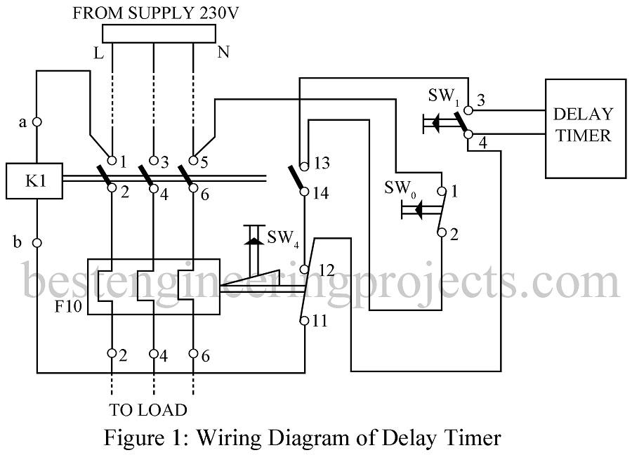
Figure 1 shows the wiring diagram and figure 2 the circuit diagram of the delay timer. The delay is set to approximately 4 minutes. The circuit is build around the dual timer IC 556 and a triac. As shown in circuit diagram (figure 2), the starter can be starter can be started by pressing the start switch SW1. While it is not pressed, 230V AC is available across SW1. This voltage initiates the delay timer and after the set delay, the triac which is across the start switch SW1 is switched on. 230V AC appears across the contractor coil K1 and the starter automatically starts.
230V AC is stepped down suitably by resistor R1, rectified and filtered using diode D1 and capacitor C1. The charging of capacitor C2 is delayed due to D3 and R2. Therefore, the voltage across capacitor C2 is low. This low voltage triggers IC1(A) and the output of IC1(A) goes high. When the output becomes 8.2V, capacitor C2 starts charging. The output of IC1(A) stays high for a period determined by R3 and C4 and then it goes low.
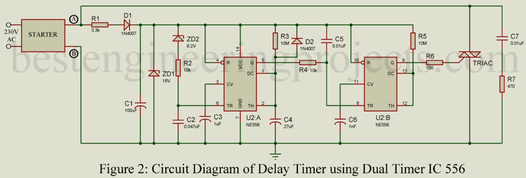
This low voltage triggers IC1(B). The output of IC1(B) goes high and triggers the triac. This short circuits the start switches and the starter is started. Now, there is no supply to the timer circuit as the voltage across the starter is 0V. The total delay is approximately 4 minutes. Diode D4 is provided for the immediate discharge of capacitor C4. Capacitor C7 and resistor R7 from the snubber network to protect the triac.
PCB Diagram:
PCB Diagram of Delay Starter using IC 556 is designed using Proteus 8.1 design suite. Actual size solder side and component side is shown in figure below. Download the PCB in PDF format from the link below.
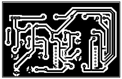
Figure 3: Solder Side PCB of Delay Starter using 556 Dual Timer IC
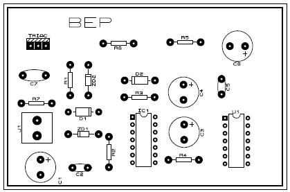
Figure 4: Component side PCB of Delay Starter using 556 Dual Timer IC
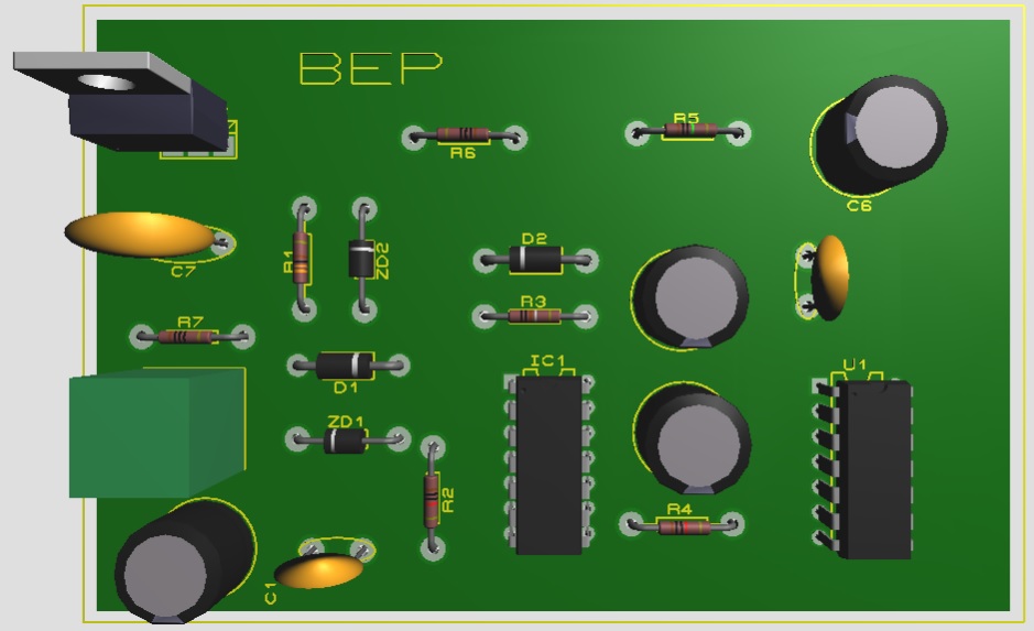
Figure 5: 3D view of Delay Starter using 556 Dual Timer IC
PARTS LIST OF DELAY STARTER USING IC 556
| Resistors (all ¼-watt, ± 5% Carbon else Specified) |
| R1 = 3.3KΩ, 5W
R2, R4 = 10 kΩ R3, R5 = 10 MΩ R6 = 100 Ω R7 = 470 Ω |
| Capacitors |
| C1 = 100 µF, 40V (Electrolytic Capacitor)
C2 = 0.047 µF (Ceramic Disc) C3, C6 = 1 µF, 63V (Electrolytic Capacitor) C4 = 27 µF, 63V (Electrolytic Capacitor) C5 = 0.01 µF (Ceramic Disc) C7 = 0.01µF, 400V (Ceramic Disc) |
| Semiconductors |
| IC1 (A, B) = NE 556 (Dual Timer IC)
D1, D4 = 1N4007 (General Purpose Rectifier Diode) ZD1 = 16V, 400mW Zener Diode ZD2 = 8.2V, 400mW Zener Diode TRIAC1 = T830-8FP |
| Miscellaneous |
| SW0 = OFF Push Switch
SW1 = ON Push Switch SW4 = RESET Push Switch K1 = Contractor F10 = BIMETAL Relay |
Various other timer circuit posted in bestengineeringprojects.com
- Sound Activated 0-30 Minutes Timer Circuit
- Industrial Timer Circuit
- Countdown timer using arduino
- Programmable Timer Circuit