Humans are born of habits, they want more and more comfort. To match their requirements, various types of automatic control systems have been developed. Now, again here we have come up with a very interesting project called “Industrial Timer Circuit” with facilities like automation and switching, providing delay and having a long-range of control (100 m).
A simple timer circuit can be designed using 555 timer IC by configuring it into monostable mode. These types of circuits have various types of limitations like digital display, an indication of system failure, remote (wireless operation), alarm, etc. The above-listed limitation can be overcome using the project “Industrial Timer Circuit”.
Before starting a discussion on circuit description and working, here we have listed some features of the Industrial Timer Circuit.
Features of Industrial Timer Circuit
- Initialization and switching process after desired or predefined time with delay facility.
- 1 to 60 seconds can be set which can be extended by editing software code.
- On/Off time is programmable thus one can program time from 1 to 60 seconds.
- A facility like single or continuous mode is available.
- Wireless remote facility with a range of 100m.
- For a better user interface, an LCD with front-panel control is available.
- An emergency stops buttons to avoid any unusual operation in both the control panel as well as in the transmitter circuit.
Check out other interesting timer projects posted on bestengineeringprojects.com
- Sound Activated 0-30 Minutes Timer Circuit
- Pulse Generator Cum Timer Circuit
- Countdown Timer Using Arduino
- 24 Hour Digital Clock and Timer Circuit
- Digital Clock with Seconds and Alarm Time Display
Circuit Description of the industrial timer circuit
The circuit of “Industrial Timer Circuit” is divided into two main sections i.e. transmitter and control section. Here at first let’s discuss the transmitter section.
Transmitter Section | Industrial Timer Circuit
The circuit diagram of the transmitter section is shown in figure 1. The entire circuit is built around encoding IC HT12E (IC5) and 433 MHz radio frequency transmitter module with some other electronic components for working flawlessly. To set address ‘00h’ all the address pins of IC5 are connected to the ground as shown in the circuit diagram. The data pin of the RF transmitter is connected to Dout pin (pin 17) where a 1 M resistor is connected to the oscillator pin (pin 15 and 16) of IC5. Four push-to-on switches (switch SW10 to SW13) are connected to the data input pin through diodes. The function of the keys is listed in table 1. Where LED (LED3) is used to indicate whether the switch is pressed or not. Pin no 14 (TE) pin is connected directly to the ground through switch SW14.
![]()
For less complexity, we further divided the control circuit into two main sections i.e. receiver section and the control section.
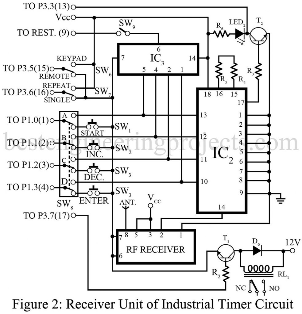
Receiver Section | Industrial Timer Circuit
The circuit diagram of the receiver section is shown in figure 2. It includes decoder IC HT12D (IC2), RF receiver module, and 4-input NAND gate IC. Al the address pin of IC2 is connected to the ground to set address ‘00h’ as in the transmitter section. The data pin of IC2 is connected to the microcontroller through a 4PDT switch SW8 and connected to the input of the 4-input AND gate IC (IC3) as shown in figure 2. The output of AND gate IC is connected to the reset pin through the ON/OFF switch SW9. LED2 is used to indicate the reception of data from the transmitter. Two resistors R4 and R5 are connected between oscillator pins (pin 15 and pin 16). Here we used a series connector to get a 51K-ohm resistor. The output pin of RF receiver RX1 (pin 2) is connected to the DIN pin (pin 14) of IC2.
Control Section | Industrial Timer Circuit
The circuit diagram of the control section is shown in figure 3. It includes a microcontroller AT89C51, an LCD, and a few other electronic components like resistors, capacitors, transistors,s, etc. An LCD is connected to the microcontroller through Data pin D0 to D7 as shown in the figure. Where a variable resistor VR1 is used to control the level of contrast. A crystal oscillator is connected to the XTAL pin (pins 18 and 19) to generate clock frequency. A switch is connected to the reset pin of IC1 (pin 9) to reset the process. A resistor R5 is used as a pull-up resistor to control the switch bounce.
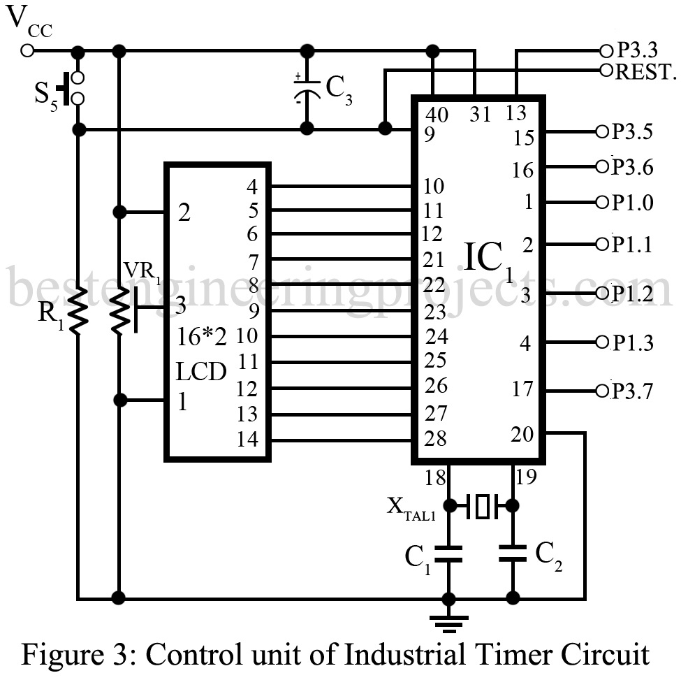
Programmable pin P3.7 (17) is connected to the base of transistor T2 through resistor R2 to switch on the relay RL1. Relay RL1 is used to switch on or off the appliance.
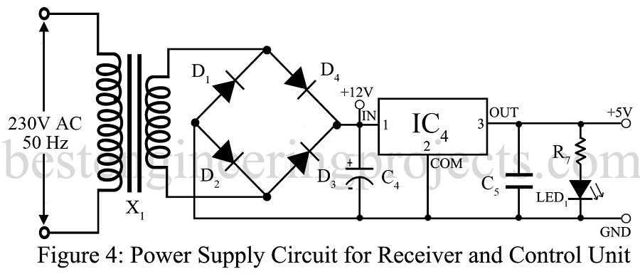
Power supply | Industrial Timer Circuit
The circuit diagram of the power supply is shown in figure 4. The input 230V, 50Hz ac input voltage is stepped down to 12V, 50Hz using transformer X1. This 12V output is changed to 12V DC using a bridge rectifier (made from 4 general purpose rectifier diodes D1 to D4) and a filter capacitor C4. The filtered 12V DC output is changed to +5V regulated power supply using a series voltage regulator IC (IC4). The power supply circuit shown here can provide two different power supplies (+12V and +5V) as shown in the circuit diagram.
Operation of Industrial Timer Circuit
Here we have described how the system operates. The properties and working of switches are listed below in table 1. Switch SW7 is used to select the mode of operation i.e. Single-mode or repeat mode. In single mode, the sequence of on and off time will run once but in repeat mode the sequence repeats. When an interruption occurs during the operation, say when a switch is SW7 is changed to single-mode from repeat mode, the time stops only after the cycle completes.
In a time of emergency, switch SW5 is pressed to stop the timer operation.
| Table 1
Function of Switches |
||
| SW1 | Start | Start timer operation |
| SW2 | Inc. Time | Increment time set by 1 sec. max limit is 60 |
| SW3 | Dec. Time | Decrement time set by 1 sec. min limit is 1 |
| SW4 | Enter | Used to enter time set value |
| SW5 | ES (RST) | Emergency stop or system reset. |
| SW6 | Control Selection | Selection of either remote or keypad control. |
| SW7 | Mode Selection | Selection of either repeat or single control. |
| Table 2
Status of Data Input Pins and the Codes Transmitted |
|||||
| Switch | D3 | D2 | D1 | D0 | Code |
| Start | 0 | 1 | 1 | 1 | 7 |
| Inc. time | 1 | 0 | 1 | 1 | B |
| Dec. time | 1 | 1 | 0 | 1 | D |
| Enter | 1 | 1 | 1 | 0 | E |
| ES | 1 | 1 | 1 | 1 | F |
Procedure for step by step configuration
- Switch on the device
- A message ‘Enter on time’ will appear on the LCD.
- One can select the desired time by pressing switch SW2 (for decreasing) and SW3 (for increasing).
- Enter switch (SW4) is used to set the time and further ask to enter ‘off’ time same as in setting desire time using switches SW2 and SW3.
- A message ‘Press start’ on display appears and operation will start after pressing switch SW1.
- Till on time the relay RL1 is energized as a result the device is switched on when the time countdown to zero the relay is de-energized and the device will turn off.
Software: Click here to Download Software Code
PARTS LIST OF INDUSTRIAL TIMER CIRCUIT
| Resistors (all ¼-watt, ± 5% Carbon) |
| R1 = 10 KΩ
R2, R3, R7 = 1 KΩ R4 = 3.9 KΩ R5 = 47 KΩ R6, R8 = 330 Ω VR1 = 10 KΩ Preset |
| Capacitors |
| C1, C2 = 33 pF (Ceramic Disk)
C3 = 1 µF, 16V (Electrolytic Capacitor) C4 = 1000 µF, 25V (Electrolytic Capacitor) C5 = 0.1 µF (Ceramic Disk) |
| Semiconductors |
| IC1 = AT89C51 Microcontroller
IC2 = HT12D decoder IC3 = 74LS21 four input AND gate IC4 = 7805, 5V regulator IC5 = DHT12E encoder T1 = BC 337 NPN transistor T2 = BC547 NPN transistor D1 – D5 = 1N4007 Rectifier Diode D6 – D13 = 1N4148 Switching Diode LED1 – LED3 = 5mm LED LCD = 2-line and 16-character LCD TX1 = 433MHz ASK Transmitter Module TX2 = 433MHz ASK Receiver module |
| Miscellaneous |
| X1 = 230V AC Primary to 12V, 500mA Secondary Transformer
XTAL = 12MHz Crystal SW1 – SW5, SW10 – S14 = Push-to-on tactile switch SW8 = 4PDT Toggle Switch SW9 = SPST Toggle Switch RL1 = 12V, 1C/O relay |