The project “Sound Activated 0-30 Minutes Timer Circuit” is a simple project designed using timer IC 555 and LM324 Quad op-amp IC. By using this project, one can activate or de-activate the appliance using sound, and the time delay can be adjusted from a few seconds to 30 minutes.
Application: The applications of the project Sound Activated 0-30 Minutes Timer Circuit are:
- Used as a sound-activated burglar alarm.
- Used as timer circuit in kitchen, house.
- used for appliance operations like refrigerators, TV, Rice-cooker, etc. by adjusting the time as per required.
Circuit Description of Sound Activated 0-30 Minutes Timer Circuit:
The circuit Sound Activated 0-30 Minutes Timer Circuit is shown in figure 1. The circuit is designed around a Microphone, Quad op-amp LM324, IC555, and a few other electronic components like resistors, capacitors, diode, etc. for working flawlessly. For a better understanding of the project, the circuit is divided into three main sections.
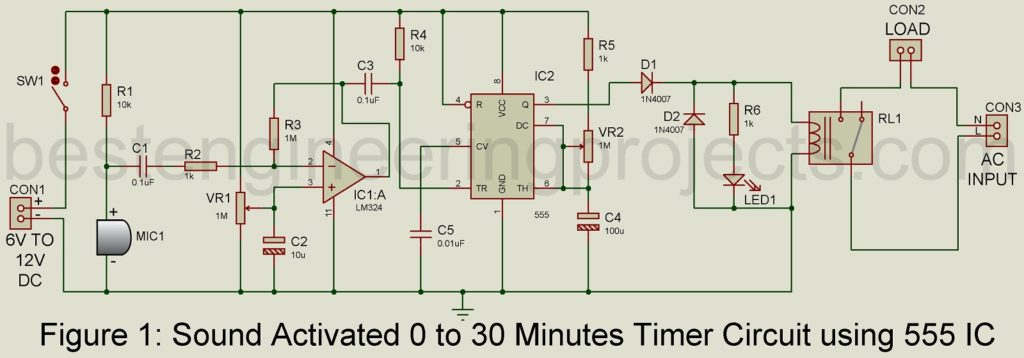
Sound Detector and Amplifier Section:
The sound detector and amplifier section are designed around a condenser microphone (MIC1) and Quad op-amp IC LM324. Microphone MIC1 detect sound signals (say clap sound) and change them into an electrical signal. This electrical signal is very small and needs further amplification. The work of amplification is done by one of the op-amps of quad op-amp LM324. The output of the microphone is given to the inverting terminal of amplifier A1 through coupling capacitor C1. The sensitivity of the microphone is adjusted using variable resistor VR1.
Timer Circuit | Sound Activated 0-30 Minutes Timer Circuit
The output of the amplifier from pin 1 is given to trigger pin (pin 2) of timer IC 555 through coupling capacitor C3. The timer IC (555) is configured in monostable multivibrator mode which is also called a one-shot multivibrator. When the microphone detects any sound signal, the output pin of IC1 becomes high and makes the trigger pin (pin 2) of IC2 high. The high at the trigger pin set the internal flip-flop of IC2 and as a result, the output at pin 3 becomes high.
The time interval of the circuit Sound Activated 0-30 Minutes Timer Circuit is dependent on the RC component connected to pin 7 and pin 8 of IC2 i.e. R5, VR2, and capacitor C4. By adjusting one of these three components the time interval changes. It is quite tedious to change the value of a capacitor and a fixed resistor. Thus, we had to use a variable resistor to change the value of the resistor and finally change the time interval.
Another interesting timer circuit posted on bestengineeringprojects.com
- Industrial Timer Circuit
- Pulse Generator Cum Timer Circuit
- Countdown Timer Using Arduino
- 24-Hour Digital Clock and Timer Circuit
- Digital Clock with Seconds and Alarm Time Display
Switching Circuit | Sound Activated 0-30 Minutes Timer Circuit
The switching circuit is designed using a relay and diode. The relay is an electromagnetic device that uses a low-current electrical signal to a current high-power electrical appliance. The high output at pin 3 energizes relay RL1 for a time interval set by variable resistor VR2. Glowing LED1 indicates the relay is energized (i.e. load is active), where resistor R6 is a current limiting resistor that protects LED from burnout due to high current. Diode D2 is a fly-back diode and protects the coil of the relay. The load is connected to connector 2 (CON2) where AC mains are given to connector 3 (CON3). The DC power supply is connected to connector 1 (CON1).
NOTE: The voltage rating for the relay must be the same as the DC power supply given to the circuit. If the DC volt given to the circuit is 6V then the relay also must be 6V. Similarly, if the DC volt is 12V then the relay also must be 12V.
PARTS LIST OF SOUND ACTIVATED 0-30V MINUTES TIMER CIRCUIT
| Resistors (all ¼-watt, ± 5% Carbon) |
| R1, R4 = 10 KΩ
R2, R5, R6 = 1 KΩ R3 = 1 MΩ VR1, VR2 = 1 MΩ |
| Capacitors |
| C1, C3 = 0.1 µF (Ceramic Disc)
C2 = 10 µF/16V (Electrolytic Capacitor) C4 = 100 µF/16V (Electrolytic Capacitor) C5 = 0.01 µF (Ceramic Disc) |
| Semiconductors |
| IC1 = LM324 (Low power quad operational amplifier)
IC2 = NE555 (Timer IC) D1, D2 = 1N4007 (Rectifier Diode) LED1 = 5mm any color LED |
| Miscellaneous |
| RL1 = 6V – 12V Relay
MIC1 = Condenser Microphone SW1 = ON/OFF Switch CON1, CON2, CON3 = Two pin connector Power Supply = 6V – 12V DC power supply |
hello… I’m from Indonesia, can this circuit be used with the sensor not from the mic but from the 3.5 phone plug directly? so i can use schedule from phone for this
Thank you in advance
I put the 10K bias resistor on a switch so I could plug in a mic or a line level signal.
Hello. Thanks for posting this schematic and details. I’ve built it and it works good. I had a question – is it possible to convert to bipolar power? I used a LM358 instead of a 324. Would I just wire negative voltage in place of ground, on the op amp?
if you are using LM358 there is no need a negative power supply.
Hello. I agree. I asked because I wanted to experiment with audio filtering circuits (specifically, a bandpass stage) which typically run off a bipolar voltage, and wanted to avoid ground issues from using a split rail config and single battery supply. Your circuit is one of the nicer ones out there, so I was curious about the conversion of your circuit. But as I look into this and learn some things, I think I have other ideas to try.
Thanks for your reply and time.