Before continuing about troubleshooting of traveling wave tube amplifier we have some initial considerations include:
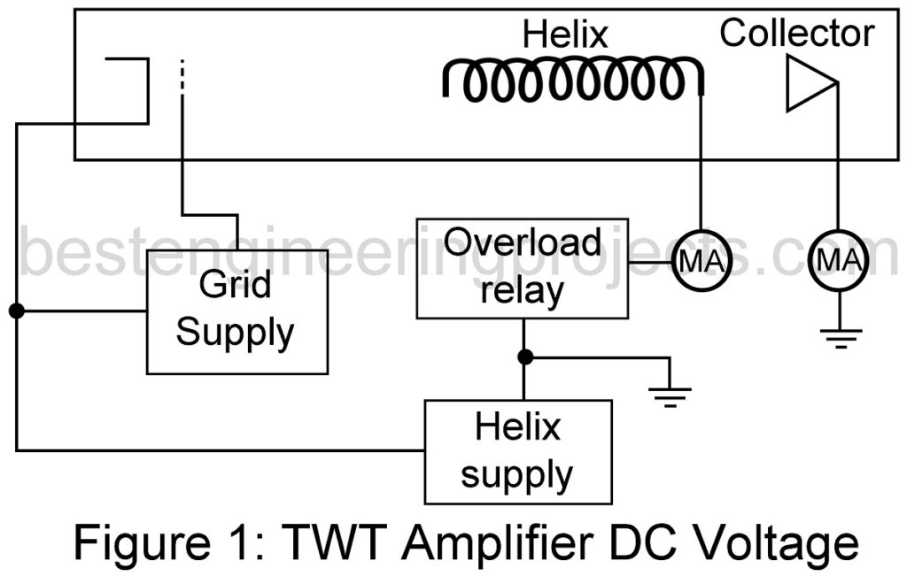
- To make construction of the tube RF output circuit simple, the collector and helix are grounded. The cathode will be above ground and have a negative voltage on it as shown in figure 1.
- The helix is delicate and helix current will be small. The collector draws nearly all the current. The helix will be protected with an over current relay that kills the power supplies. Never defeat this relay because the tube can be lost in almost zero time.
- Always operate the TWT amplifier into a good dummy load. High VSWR will cause high helix current. The RF input should also be terminated.
TYPICAL DC PROBLEMS
- Low gain. Gain is a function of helix voltage. Make sure it is correct.
- Amplifier will not stay on and overload relay trips. Check the overload trip point with an external power supply and milliampere meter as shown in figure 2. The relay contacts should open when the desired overload current is reached. The resistor may be potentiometer. You will find the specification for helix current in the TWT manual. Check all power supply components with the power off. If you cannot find the problem, you may have to construct a bank of resistors to use in place of the tube to troubleshoot the power supplies while they are operating.
- Excessive collector current. Make sure the grid supply is OK. Remember, both sides of the grid supply are above ground.
- We cannot turn the helix supply on. Look for malfunctioning fault relays. TWTs usually have relays that turn the power supplies on in a sequence: heater first, grid next, and helix last.
- Superior modulation. Hum or ac ripple on the power supplies will modulate the RF output. The helix supply will be a regulated supply and should have almost no hum. Check this with no oscilloscope with high-voltage probe.
- Power output is low. Is too much RF drive being applied? Power output of a TWT increases as drive is increased until saturation is reached. If drive is increased past that point, power output falls off.

TYPICAL RF TROUBLES
- Poor frequency response or low gain. Most TWTs have RF bandpass filter in the input to correct the frequency response of the tube. Check the filter for excessive loss at the center frequency and for power bandpass response. Generally, there should be a loss of several dB at the band edges are very little loss at the band center.
- Low RF output. At microwave frequencies, coaxial cables and connectors cause a lot of trouble. Assembly procedure is critical for power operation. Look for loose shield at the connectors and check for loose and VSWR. Good TWTs will have an isolator in the output circuit. Isolator should show a loss of 1 dB or less in the forward direction and at least a 20-dB loss in the reverse direction.
These components are best checked with a network analyzer and a sweep oscillator.