A Lithium-Ion Battery Charger Circuit using LM317 charges the battery in two different modes: constant current mode and constant voltage mode.
Lithium polymer or lithium-ion batteries are very prone to overcharging or charging with high voltage or high current. Thus, when designing the charger circuit for Li-ion or Li-Po, we must consider a few things, such as charging voltage and current. The circuit posted here is designed using one of the famous variable voltage regulators, IC LM317. This circuit charges the battery in two modes, i.e., constant current and voltage. In continuous current mode, the battery is charged with constant current till the voltage of the battery approaches the desired level. In constant voltage mode, the battery is charged with continuous voltage where the current approaches zero.
Li-ion or Li-Po batteries are sensitive to overcharge, deep discharge, and high temperature. If the above conditions match, it might show abnormal charters like exploding, generating fumes, etc. The Single-cell of Li-ion battery is 3.7V. This cell can be charged up to 4.2V, i.e., the total charge voltage will be 4.2V. It is also recommended not to discharge 3.4V. When we charge the li-ion/lipo battery to 4.2V, its life will be decreased by twice. So, we adjusted the charger circuit to charge the battery up to 4.1V. While charging the battery up to 4.1V, its capacity will be reduced by 10% but increase life by twice.
Circuit Description of Lithium-Ion Battery Charger Circuit
Figure 1 shows the lithium-ion battery charger circuit. It consists of a variable voltage regulator IC317, a current limiter resistor, a switching transistor, and a few other electronic components. An NPN transistor with a diode and shunt resistor (R2) stabilizes the output current.
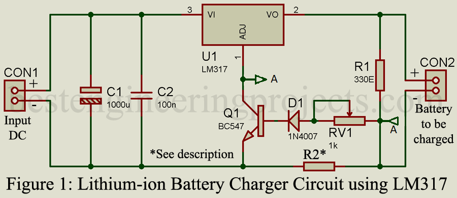
Where a variable resistor with resistor R1 is responsible for voltage output. Output voltage of this circuit 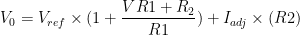 . The value of resistor R2 is minimal, in the range of a few ohms. Thus, the contribution of Iadj in voltage output is negligible. However, the charging current value depends on resistor R2 and can be calculated using a mathematical formula.

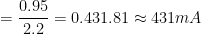
For Imax 200mA, the value of resistor 
The value 0.95 is the voltage drop across the transistor’s base-emitter pin and diode combined.
Component List of Lithium-ion Battery Charger Circuit
| Resistor (all ¼-watt, ± 5% Carbon) |
| R1 = 330Ω
RV1 = 1KΩ R2* = 2.2Ω, ½-watt |
| Capacitors |
| C1 = 1000µF, 25V
C2 = 100nF |
| Semiconductors |
| U1 = LM317 (Variable positive voltage regulator)
Q1 = BC547 (General purpose NPN transistor) D1 = 1N4007 (Rectifier Diode) |
| Miscellaneous |
| Two Terminal block |
Working of Lithium Ion Battery Charger Circuit
This charger circuit works as a constant current source till the battery voltage reaches Vo. Initially (when the battery is discharged), the battery will try to draw as much current as possible. However, resistor R2 does not allow it. When the maximum current (Imax) starts to follow through a shunt resistor, the transistor begins to conduct. As a result of voltage at adjustment, the pin reduces and makes the output current constant, i.e.  .
.
The role of the shunt resistor is to decide the value of the charging current, thus not affecting battery charging voltage. The transistor does not conduct entirely due to shunt voltage because the maximum voltage drop across does not exceed 0.95V. Therefore, the transistor loop ensures that the charging current will be constant. While charging the battery with a continuous current, the battery’s voltage will increase slowly. When the battery voltage equals the output voltage of the circuit (V0), the current approaches zero, and the voltage becomes constant.
PCB Design
The “lithium-ion battery charger circuit using LM317” PCB was designed by an Altium designer. Figure 2 shows the solder side, component side, and 3D design. The actual-size solder-side and component-side PCB in PDF format can be downloaded from the link below.
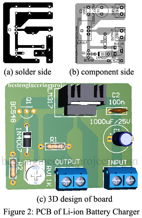
Click here to download the PCB.
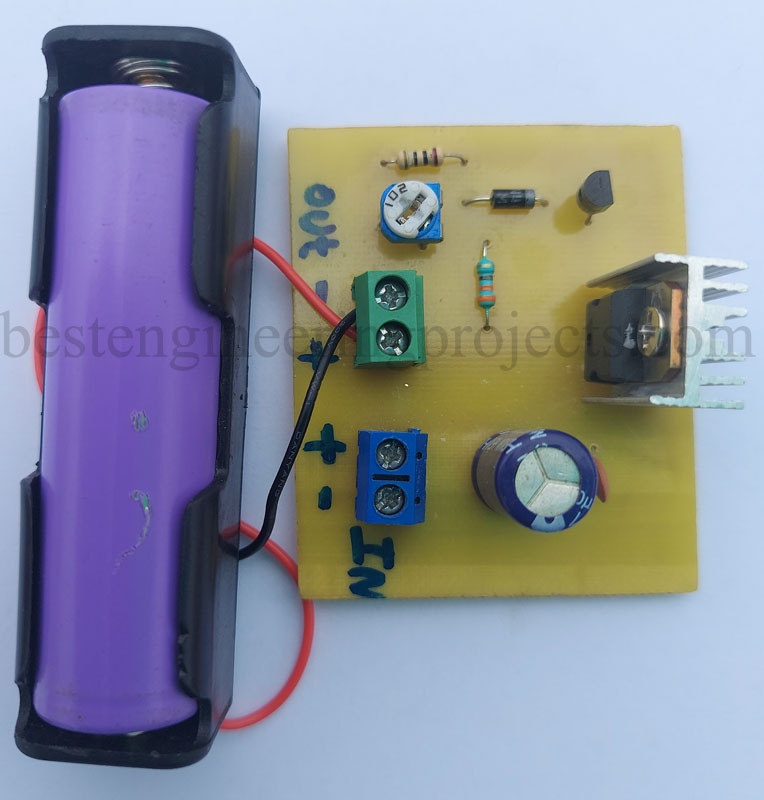
Figure 2: Author Prototype of Charger Circuit
Calibration:
Step 1: Disconnect the battery to be charged
Step 2: Connect the DC power supply to the input.
Step 3: Adjust the variable resistor till you get full charge voltage at the output terminal. (For 3.7V, the Li-ion output voltage will be 4.2V, but here, we will set it to 4.1V to increase the battery life).
Step 4: Connect the battery.
Note: Use the proper heatsink for LM317.
The schematic is different from the description, Why ?!!!
The description is for the circuit posted in that article. Please specify the unmatched line/paragraph.
Thankyou.
Rx and R3 ARRE mentioned in the decription but do not appear on the circuit.
I appreciate
What about the input voltage? Can i use 12v?
The input voltage will be between 6V and 32V.
Yes, you can use 12V.
If am using 12v 5A charge what will be the out put current using this your circuit?
The circuit designed here is to deliver max. current of 200mA.
Very simple circuit. I built one just like this for a small adj voltage power supply years ago. I knew the LM317 was a good be a great component for charging a lipo. So when I googled the charger I was glad to see this very similar circuit at the top of the list
Link to PCB, not working