Today in this article we are going to show you the circuit diagram and description of the 5 Band Audio Equalizer Circuit using LM833. We already control 8W + 8W Stereo with a graphic equalizer, but this time we come with 5 Band Audio Equalizer Circuit. First, let’s talk about what an equalizer is.
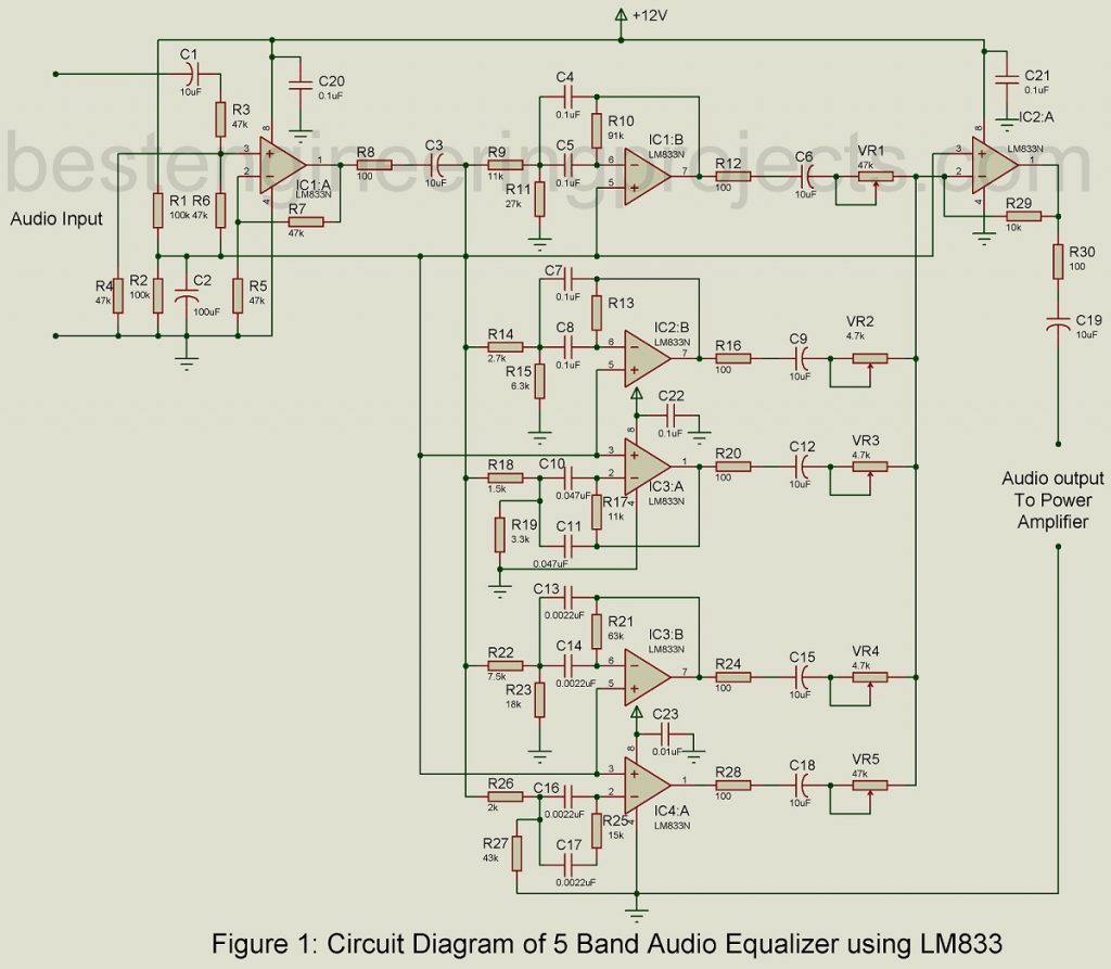
5 Band Audio Equalizer Circuits using LM833
Equalizer circuits are those circuits that are responsible to maintain a balance between the frequency components. The project 5 Band Audio Equalizer Circuit using LM833 divides the audio spectrum into multiple frequency bands. The gain control of each band can be adjusted as per requirement separately. A separate IC4 is used to mix the output signals obtained from each frequency band and the mixed output is then fed as input to the audio power amplifier. The output might be disrupted due to overlapping of signals obtained from different sources and to avoid a suitable quality factor (Q) must be selected, doing so introduces coloration into the audio signal.
The band graphic equalizer circuit is constructed using two cheap and good-quality operational amplifiers which are readily available in the market. These op-amps feed on a single voltage supply which is another advantage to the user. However, the operational amplifiers must meet certain requirement standards, they should have a noise density of less than 24nV/ VHz, a slew rate of more than 5V/µs, and a gain-bandwidth product greater than 3 MHz. If available, you can use op-amps NE5532 or LM833 which fulfill our requirements to a greater extent.
Components Values of 5-band Equalizer
|
Components Values for 5-Band Equalizer |
||||||
| Centre frequency f0 (in Hz) | Capacitor value (in uF) | Resistors Ra value (in K) | Resistors Rb value (in K) | Resistors Rc value (in K) | Gain (A) | Quality (Q) |
| 60 | C4 = C5 = 0.1 | R9 = 11 | R11 = 27 | R10 = 91 | 4.1 | 1.7 |
| 250 | C7 = C8 = 0.1 | R14 = 2.7 | R15 = 6.3 | R13 = 22 | 4.1 | 1.7 |
| 1000 | C10 = C11 = 0.047 | R18 = 1.5 | R19 = 3.3 | R17 = 11 | 3.7 | 1.6 |
| 4000 | C13 = C14 = 0.0022 | R22 = 7.5 | R23 = 18 | R21 = 63 | 4.2 | 1.7 |
| 16000 | C16 = C17 = 0.0022 | R26 = 2 | R27 = 4.3 | R25 = 15 | 4.2 | 1.7 |
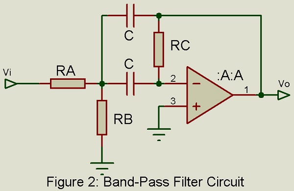
For the development of the band graphic equalizer circuit, we have utilized the multiple-feedback bandpass filter topology, the figure of which is given in the left-most corner at the bottom of the figure. The figure includes a prototype for a single-channel bandpass filter. If you decide to use the capacitors of the same value as we have listed in the project, it will be easier to make rough calculations in the project. You are familiar with these formulas, I think. They help us to choose our components accordingly for the desired effect in the final result. Here are those formulas:
The formula used in this Projects


Using these basic formulas, other formulas are also generated to find component values for the remaining.


How do choose components’ Values?
On the basis of the capacitor value used in the circuit, select different values of resistors used in the project. So, the first step is choosing the capacitor value. Choose a capacitor with a high capacitance of about 0.1F and a resistor with resistance as small as to fit. Capacitance is inversely proportional to the resistance value and thus a high capacitance results in smaller resistance values for all three resistors used in the project.
There are multiple factors that might affect the performance of the project, and hence the areas where circuit failure is likely must be taken care of. In the input buffer op-amp, there might be chances of overloading, the overall capacitance of the circuit can be possibly reduced by the stray capacitance generated through the board. It will reduce the resistance to a much lower value. However, resistance Rb doesn’t influence the bandwidth and gain of the circuit and thus is used to alter the mid-frequency of the circuit.
The mid-frequencies are standards used in band graphic equalizers. The value of these frequencies varies according to different parameters like the octave division, application, and manufacturers’ preference, since most of the devices include the same octave rules, the center frequency is fixed at 1000 Hz.
Balance Between Filters and Bandwidth
Referring to the project title; equalizer, one must monitor the balance between the filters used and their bandwidth. We can compromise in some situations with the number of filters. With a wide range of bandwidths, we can use fewer filters and more filters with a narrow bandwidth. With the increase in quality factor(Q) of the filters, the complexity of the circuit also increases, and thus using a filter with a narrow bandwidth of less than 1/3 octave is rare and not wise as well. Doing so adds to the cost and limited applications of the circuit.
National Semiconductor has defined a standard, to build a 10-band graphic equalizer circuit, the range of mid-frequencies that can be used are 32, 64, 125, 250, 500, 1k, 2k, 4k, 8k, and 16k. Similarly, a quality factor of 1.7 is desired.
For a particular center frequency of the circuit, component values are listed in the table. The gain factor (A) of 4 is preferred.
Circuit Description of 5 Band Audio Equalizer using LM833
The band graphic equalizer circuit provides five bands control, the project circuit is centered around the IC1 (A) LM833 as the buffer stage. This IC has a gain factor of 2 and is a non-inverting amplifier. Two resistors R3 and R4 form up the resistive network and this network divides the input signal by 2. For this reason, the amplifier has a net gain factor of unit value.
Resistors R1 and R2, each of 100k value build up the voltage divider section, and the voltage obtained at the junction of these two resistors is fed to its positive input terminal through another resistor R6. The power possessed by the voltage divider circuit is adequate enough to operate the op-amps used in the project if needed. Another resistor; Ro (R8=R12=R16=R20=R24=R28=R30=100Ω) is included in the project that serves the dual purpose of reducing noise effects and tasks concerning resistive isolation of capacitive load. The value of the resistor can be adjusted between the values of the range 50-150 ohms as per the noise in the circuit.
Five potentiometers are also included in the circuit; VR1 through VR5 along the signal path, the high-quality potentiometer is preferred. The potentiometer must be wrapped with bare copper wire around the body and the other end of the wire must be soldered to the ground. The metal-film type resistors and polyester type capacitors must be used in the project with sensitive filters.
Operational Amplifier Stage
The op-amp stages must be capacitively coupled with each other so as to avoid any chances of the DC signal being propagated or amplified. A coupling capacitor of a value greater than 1 µF is suitable for low-frequency response. In between the op-amp stages, a 10µF, 16V capacitor is used to avoid output failure.
To power the entire circuit and its components, a regulated 12V DC supply is used. To avoid the noise effect, connect a 0.1 µF ceramic disk capacitor in between the Vcc pin of each op-amp and the ground.
PARTS LISRT OF 5 Band Audio Equalizer Circuit using LM833
| Resistors (all ¼-watt, ± 5% Carbon) |
| R1, R2 = 100 KΩ
R3 – R7 = 47 KΩ R8, R12, R16, R20, R24, R28, R30 = 100 Ω R9, R17 = 11 KΩ R10 = 91 KΩ R11 = 27 KΩ R13 = 22 KΩ R14 = 2.7 KΩ R15 = 6.3 KΩ R18 = 1.8 KΩ R19 = 3.3 KΩ R21 = 63 KΩ R22 = 7.5 KΩ R23 = 18 KΩ R25 = 25 KΩ R26 = 2 KΩ R27 = 43 KΩ R29 = 10 KΩ VR1 – VR4 = 4.7 KΩ |
| Capacitors |
| C1, C3, C6, C9, C`12, C15, C18, C19 = 10 µF, 16V (Electrolytic Capacitors)
C2 = 100 µF, 16V (Electrolytic Capacitors) C4. C5, C7, C8, C20 – C23 = 0.1 µF (Ceramic Disc) C10, C11 = 0.047 µF (Electrolytic Capacitors) C13, C14, C16, C17 = 0.0022 µF (Electrolytic Capacitors) |
| Semiconductors |
| IC1 – IC4 = LM833 (Dual High-Speed Audio Operational Amplifier) |
Hello. Could you provide the schematic file of the 5 band eq project, please?
We had already posted schematic diagram as shown in figure 1.
I mean schematic(.sch) file of the CAD software
5 Band Audio Equalizer Circuit using LM833, Fig. 1
https://bestengineeringprojects.com/5-band-audio-equalizer-circuit-using-lm833/
Should IC4A-1 feedback to the RC network as it does for IC3A-1 in order for the circuit to function properly?
What is the voltage rating for the electrolytic capacitors?
Thank you…