Today, I am going to teach you how to make an LED matrix display using Arduino. Here we had designed a 7×5 LED matrix display but can be extended as per desire. If you are using Arduino uno board the number of rows can be extended up to 14 and the number of columns can be extended up to 6. This is because there are only 14 digital pins (D0 to D13) and 6 analog pins (A0 to A5). Thus, you can make a 14×6 Led matrix display in the same manner posted here.
Multiplexing Techniques | LED Matrix Display using Arduino
Before going to the circuit description part, we would like to describe multiplexing techniques used in a matrix display. Let, us suppose a 5×5 LED matrix display and you wish to glow a single LED say 7th LED then the entire row consisting of LED 7 is activated (row 3rd) as a result one lead of all LEDs of that row gets voltage. Now to glow LED 7, the corresponding column (4th column) is activated. As a result, only LED 7 starts to glow.
Circuit Description of LED Matrix Display using Arduino:
The circuit diagram of the 7×5 LED matrix display using Arduino is shown in figure 1. The entire circuit of LED matrix is built around Arduino uno board, few NPN bipolar junction transistors (7 nos. in 7×5 display), a few numbers of resistors (equal to the number of transistor i.e. 7), and LEDs (7×5 = 35 nos.). The control unit of the 7×5 LED matrix display is Arduino uno board which not only specifies the address of LEDs but also controls their timing according to source code.
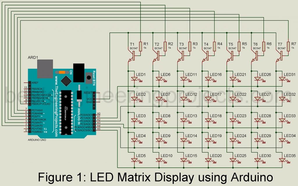
The Arduino uno board cannot use these all LEDs directly. To switch them all LEDs, we had used a switching circuit built around 7 different transistors. The output is taken from digital pin D2 through D8 and is given to the base of transistors T1 through T7. Seven resistors R1 through R7 are used as coupling between these transistors and Arduino uno digital pins. These resistors are used here to limit the current and protect transistors from burning.
The collector of the transistor is connected to a +5V supply from the Arduino board. There are altogether 7 rows and 5 columns. The anode of each column is shorted and connected to the emitter of the transistor as shown in the circuit diagram. Where the cathode of each row is shorted and connected to an analog pin for ground potential.
The flicker effect on LEDs is due to rapid switching ON and OFF transistors. We had used this technique to avoid the overloading effect of the Arduino board at the time of activating all columns.
Working of the circuit | ED Matrix Display using Arduino
To glow a LED, its corresponding digital pin (column) is set to high and its corresponding analog pin (row) is set to low. When the digital pin becomes high corresponding transistor is turned on as a result collector voltage (+5) is available at the anode of LEDs and the analog pin behaves as ground, as a result, a closed path is formed and the current starts to glow.
Method of Display character:
Here we are going to show you how to display characters in a 7×5 multiplexing display. For demo purpose, we are displaying three-character BEP (short form of Best Engineering Projects)
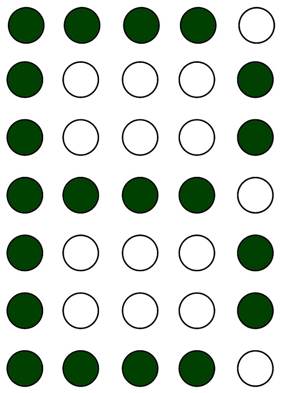
For displaying B character, you have to glow following LEDs
|
1 2 3 4 5 6 7 8 9 10 11 12 13 14 15 16 17 18 19 20 21 22 |
ledon(0,0);delay(1); ledon(1,0);delay(1); ledon(2,0);delay(1); ledon(3,0);delay(1); ledon(4,0);delay(1); ledon(5,0);delay(1); ledon(6,0);delay(1); ledon(0,1);delay(1); ledon(0,2);delay(1); ledon(0,3);delay(1); ledon(1,4);delay(1); ledon(2,4);delay(1); ledon(3,0);delay(1); ledon(3,1);delay(1); ledon(3,2);delay(1); ledon(3,3);delay(1); ledon(4,4);delay(1); ledon(5,4);delay(1); ledon(6,0);delay(1); ledon(6,1);delay(1); ledon(6,2);delay(1); ledon(6,3);delay(1); |
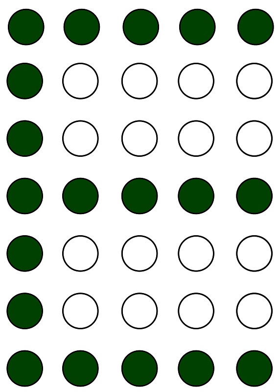
For displaying E character, you have to glow following LEDs
|
1 2 3 4 5 6 7 8 9 10 11 12 13 14 15 16 17 18 19 20 21 |
ledon(0,0);delay(1); ledon(1,0);delay(1); ledon(2,0);delay(1); ledon(3,0);delay(1); ledon(4,0);delay(1); ledon(5,0);delay(1); ledon(6,0);delay(1); ledon(0,1);delay(1); ledon(0,2);delay(1); ledon(0,3);delay(1); ledon(0,4);delay(1); ledon(3,0);delay(1); ledon(3,1);delay(1); ledon(3,2);delay(1); ledon(3,3);delay(1); ledon(3,4);delay(1); ledon(6,0);delay(1); ledon(6,1);delay(1); ledon(6,2);delay(1); ledon(6,3);delay(1); ledon(6,4);delay(1); |
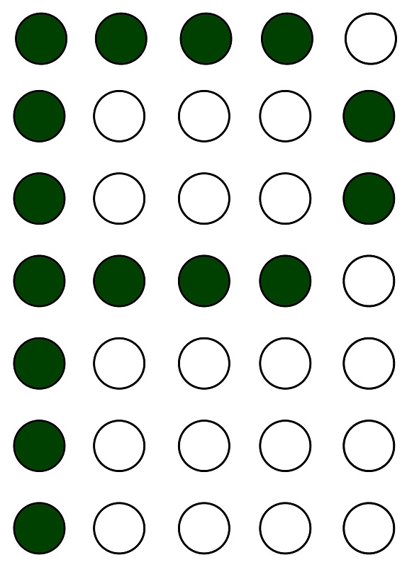
For displaying P character, you have to glow following LEDs
|
1 2 3 4 5 6 7 8 9 10 11 12 13 14 15 16 |
ledon(0,0);delay(1); ledon(1,0);delay(1); ledon(2,0);delay(1); ledon(3,0);delay(1); ledon(4,0);delay(1); ledon(5,0);delay(1); ledon(6,0);delay(1); ledon(0,1);delay(1); ledon(0,2);delay(1); ledon(0,3);delay(1); ledon(1,4);delay(1); ledon(2,4);delay(1); ledon(3,0);delay(1); ledon(3,1);delay(1); ledon(3,2);delay(1); ledon(3,3);delay(1); |
Software Code: The code of LED Matrix Display using Arduino is written in Arduino programming language and compiled in Arduino. The complete code is given below.
|
1 2 3 4 5 6 7 8 9 10 11 12 13 14 15 16 17 18 19 20 21 22 23 24 25 26 27 28 29 30 31 32 33 34 35 36 37 38 39 40 41 42 43 44 45 46 47 48 49 50 51 52 53 54 55 56 57 58 59 60 61 62 63 64 65 66 67 68 69 70 71 72 73 74 75 76 77 78 79 80 81 82 83 84 85 86 87 88 89 90 91 92 93 94 95 96 97 98 99 100 101 102 103 104 105 106 107 108 109 110 111 112 113 114 115 116 117 118 119 120 121 122 123 124 125 126 127 128 129 130 131 132 133 134 135 136 137 138 139 140 141 142 143 144 145 146 |
int RowLed[7] = {2,3,4,5,6,7,8}; //Cathode connection points int colLed[5] = {15,16,17,18,19}; //Anode connection Points int Rpin = 6; //Total cathode pins int cpin = 4; //Total anode pins void setup() { for (int i = 0; i <= Rpin; i++) { pinMode(RowLed[i], OUTPUT); } for (int j = 0; j <= cpin; j++) { pinMode(colLed[j], OUTPUT); } } void alloff() { for (int i = 0; i <= Rpin; i++) { digitalWrite(RowLed[i],LOW); } for (int j = 0; j <= cpin; j++) { digitalWrite(colLed[j],HIGH); } } void ledon(int x, int y) { alloff(); //first the turn off function is called to make sure that only that led is ON. digitalWrite(RowLed[x], HIGH); //Makes the anode pin of the particular LED at +5 V digitalWrite(colLed[y], LOW); //Makes the cathode pin of the particular LED at 0V } /* A function to display the letter B The corresponding leds are addressed here with a delay of 1 microsecond. */ void L_B() { ledon(0,0);delay(1); ledon(1,0);delay(1); ledon(2,0);delay(1); ledon(3,0);delay(1); ledon(4,0);delay(1); ledon(5,0);delay(1); ledon(6,0);delay(1); ledon(0,1);delay(1); ledon(0,2);delay(1); ledon(0,3);delay(1); ledon(1,4);delay(1); ledon(2,4);delay(1); ledon(3,0);delay(1); ledon(3,1);delay(1); ledon(3,2);delay(1); ledon(3,3);delay(1); ledon(4,4);delay(1); ledon(5,4);delay(1); ledon(6,0);delay(1); ledon(6,1);delay(1); ledon(6,2);delay(1); ledon(6,3);delay(1); } void L_E() { ledon(0,0);delay(1); ledon(1,0);delay(1); ledon(2,0);delay(1); ledon(3,0);delay(1); ledon(4,0);delay(1); ledon(5,0);delay(1); ledon(6,0);delay(1); ledon(0,1);delay(1); ledon(0,2);delay(1); ledon(0,3);delay(1); ledon(0,4);delay(1); ledon(3,0);delay(1); ledon(3,1);delay(1); ledon(3,2);delay(1); ledon(3,3);delay(1); ledon(3,4);delay(1); ledon(6,0);delay(1); ledon(6,1);delay(1); ledon(6,2);delay(1); ledon(6,3);delay(1); ledon(6,4);delay(1); } void L_P() { ledon(0,0);delay(1); ledon(1,0);delay(1); ledon(2,0);delay(1); ledon(3,0);delay(1); ledon(4,0);delay(1); ledon(5,0);delay(1); ledon(6,0);delay(1); ledon(0,1);delay(1); ledon(0,2);delay(1); ledon(0,3);delay(1); ledon(1,4);delay(1); ledon(2,4);delay(1); ledon(3,0);delay(1); ledon(3,1);delay(1); ledon(3,2);delay(1); ledon(3,3);delay(1); } void BEP() { for(int i=0;i<=50;i++) { L_B(); } alloff(); delay(200); for(int i=0;i<=50;i++) { L_E(); } alloff(); delay(200); for(int i=0;i<=50;i++) { L_P(); } alloff(); delay(200); } void loop() { BEP(); } |
Could you please re-upload de file?