This article is dedicated to those who want to make their high-quality low distortion 10 band graphic equalizer circuit. Before going to the circuit and it’s working let’s understand an equalizer and its types. An equalizer is simply a device that is attached to an instrument and with the help of this equalizer, we can set bass, middle, or treble.
Sound or audio has a spectrum where frequencies are classified into different ranges. So, what are these bass, middle and treble? These are the range of frequencies, where the bass is the lower frequency range, middle means the middle frequency range, and treble is the higher frequency range.
Different instruments have different frequency ranges. Let’s for an example, in any live music performance show where various instruments are being played by different musicians along with a vocalist if these sounds produced, were of the same frequency then the listener or audience cannot differentiate which sound is produced by which instruments. Hence, an equalizer helps in differentiating that this is the sound coming from a guitar, a tabla, a drum, or the vocalist’s sound.
Talking about history, in the 1920s, the use of equalizers started in the telecommunication industry. After that, in the 1930s the first variable equalizer was invented from which many audio companies in the UK were influenced. With the advancement of technology, software starbeing ted incorporated into the music industry. The equalizer along with the hardw is starincorporatedting with the software. Talking about the 21st century, maximum music software or music devices have inbuilt muequalizersizer. Now, there are several types of equalizers, some of them are, Bell, Shelving, Graphical, Semi-Parametrand ic, and Parametric equalizers. Parametric equalizers are popular but less than graphic equalizers because graphic equalizers are more popular as these are used in our mobile phones, music played rs and audio/video editing which is simply used either to boost or cut the specific frequency range improving the quality of the sound. The popularity of graphic equalizer is also because it offers more control over the quality of music than a simple tone control system.
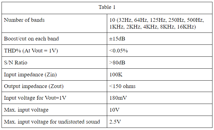
In the market, you will find a wide variety of equalizers ranging from 5 bands to 30 band equalizers. Check out the circuit of 5 Band Graphic Equalizer Circuit using LM833. Here, the circuit present is of 10 bands graphic equalizer, also famous as a first-octave graphic equalizer. This first-octave equalizer deals with 10 different frequencies ranging from 32Hz to 16KHz as shown in table 1 and is more than enough for the home system. The table I, we can see that the ratio between two adjacent frequencies is 1:2 except 64Hz to 125Hz. This is done only to round up the frequency.
Basic Equalizer Circuit
The circuit diagram of the basic equalizer is shown in figure 1. This circuit uses capacitors to fix the frequency as a result its roll-off is not sharp or step. This led to a lower cut and boost. This type of circuit also limits the gain or cut as a result there would be no relation betwthe een next or preceding frequency.
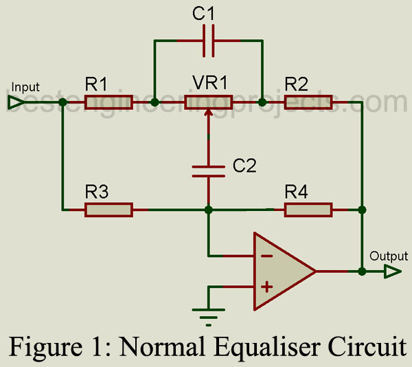
Calculation for Basic Equalizer (Figure 1)

The value of resistors R4 and R5 is usually around 1M.
Equalizer Circuit using Tuned Circuit
The equalizer circuit using a tuned circuit in the flat condition is shown in figure 2(a). This type of circuit uses a tuned circuit to fix the frequency. One can easily vary the gain and ‘Q’ of the equalizer as a result even designing a 30-band graphic equalizer is possible by using 2(a) circuits. In this circuit, the value of resistor R4 is very small in comparison to resistor R1, where the value of resistor R1 and R3 must be equal.
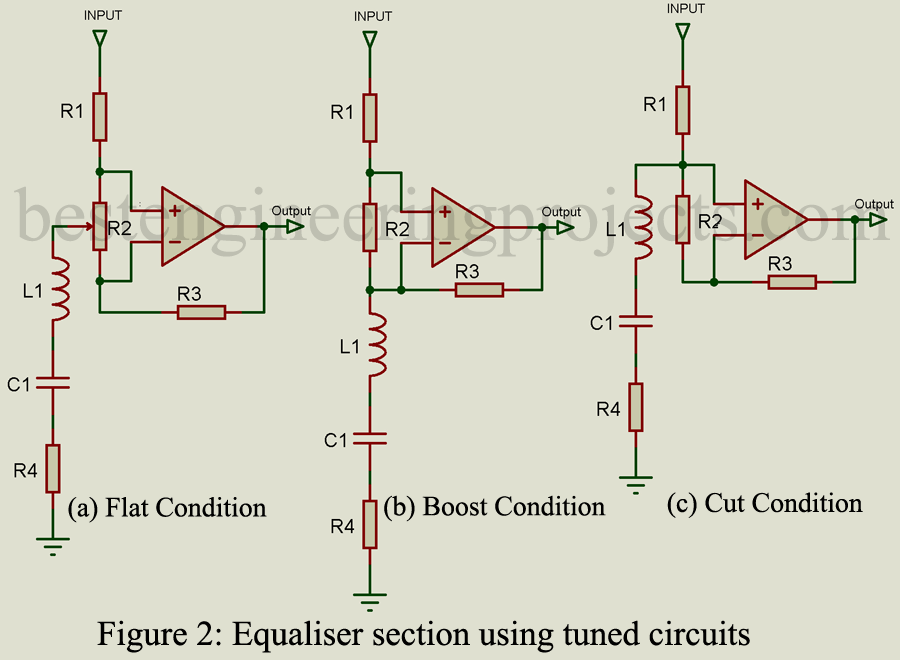
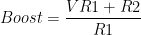
The circuit shown in figure 2(b) is in boost condition. Let us consider, the resistance of the tuned circuit below as a result the only effective resistance element is resistor R4. The gain of the circuit shown in figure 2(b) can be calculated by using the formula  . From the formula of gain, if we decrease the value of series resistor R4 high gain can be achieved. If the value of inductor L1 is increased, the effect of the one band on its adjacent band will be very very small.
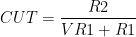
The circuit shown in figure 2(c) is in cut condition. Figure 2(a), 2(b) and 2(c) represent the same equalizer section. In figure 2(c), the input voltage is divided using two resistors R1 and R2. Some amount of input also appears at series resistor R4 because its value is very small in comparison to resistor R1. In this condition, the gain of op-amp A1 becomes zero as a result it acts as a buffer. The value of cut can be determined using relation  .
.
Let’s consider building a 10-band graphic equalizer using the concept of the circuit shown in figure 2. At lower frequencies (say 32Hz or 64Hz) the value and size of inductor L1 become very big i.e. one inductor can occupy the entire cabinet. To solve this issue, the concept of a simulated inductor is used.
Simulated Inductor
A simulated inductor is an equivalent circuit for an inductor. The basic design considering a simulated inductor is shown in figure 3(a) where figure 3(b) shows the simulated inductor incorporation in an equalizer. Capacitor C1 (figure (3a)) is the series tuning capacitor while all the other components make up the simulated inductor.
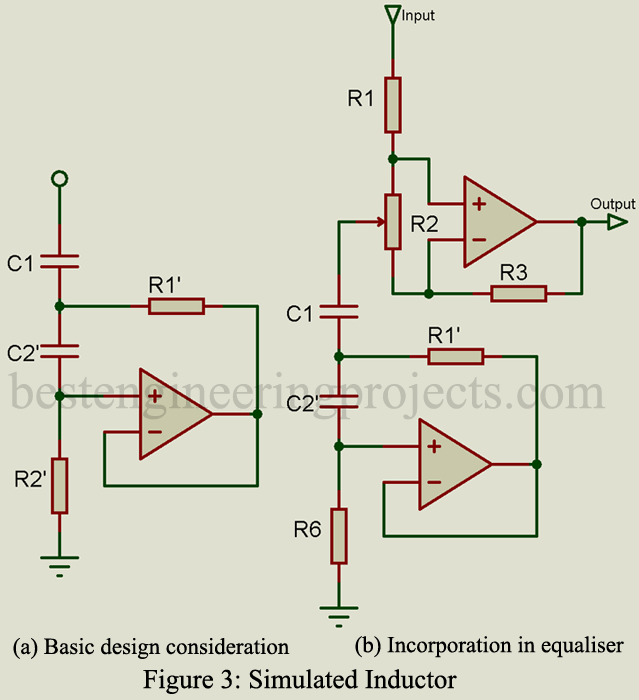
Mathematical Calculation involved in Simulator inductor

R2 = Bias resistor for A1
R2’ = Very high value like 100k or 220k


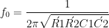
R1’ can be calculated by first selecting R3 (In figure 3(b)) and then using the rotation

Description of 10 Band Graphic Equalizer Circuit
The circuit of the 10 band graphic equalizer is shown in figure 4. It is built around three quad op-amp IC (TL084s). The input is designed around U3:A of U3 with a gain of 5.5. Capacitor C2 acts as a very high-frequency filter. The simulated inductor is designed around ten different op-amps each for individual bands (i.e. 32Hz to 16KHz). The output is designed around op-amp U5:D. All the potentiometers (VR1 to VR10) are connected to the output op-amp U5:D. These potentiometers are used to boost or cut specified frequencies. Op-amp U5:D is a replica of A1 as shown in figure 3(b).
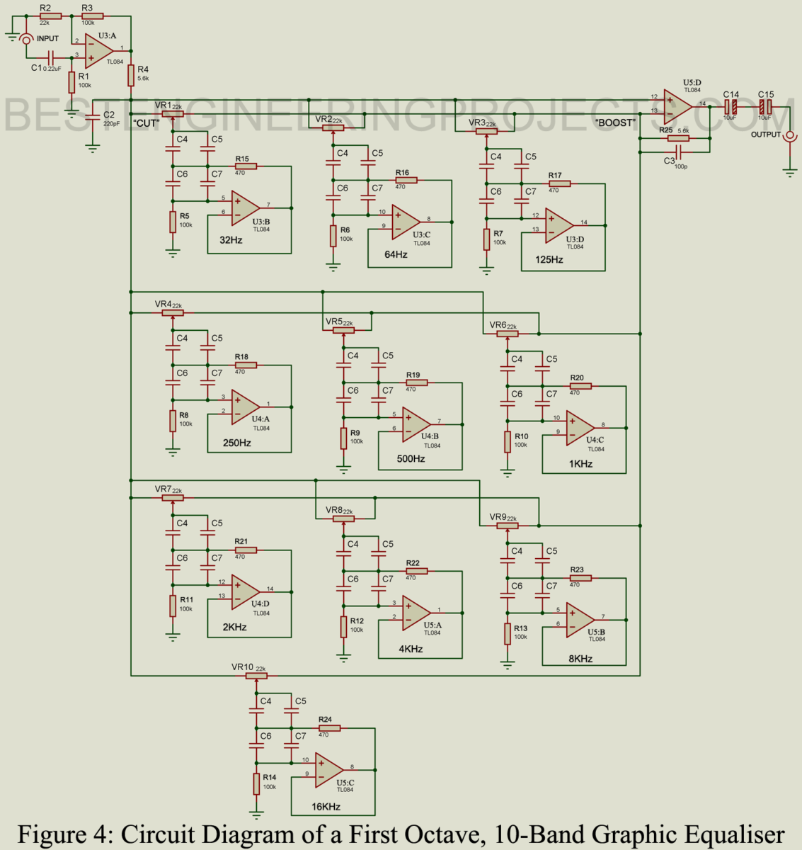
All the potentiometers used in this circuit are of logarithmic type i.e. resistance changes slowly in both the end and quickly in the middle. The reason for using this type of pot is the sensitivity of the circuit. The circuit becomes most sensitive when the value of the pot approaches 470 ohms. To solve this problem, a logarithmic potentiometer is used.
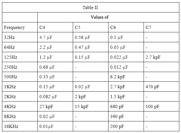
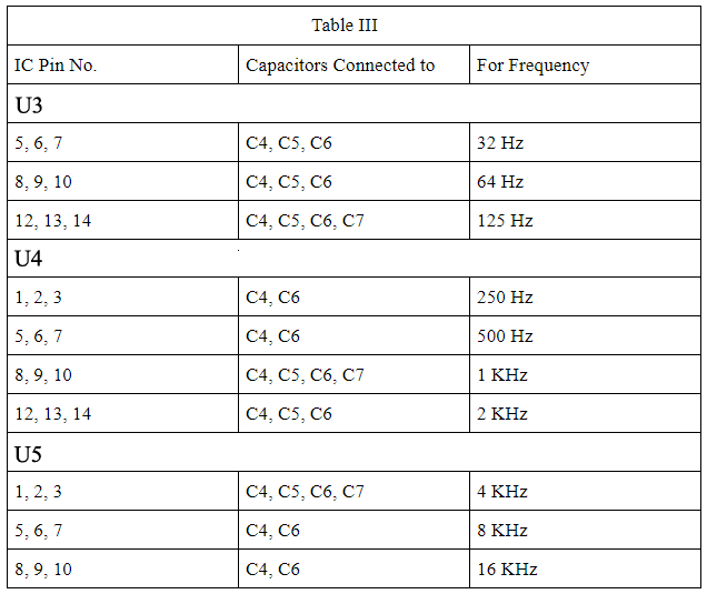
The value of the capacitor is shown in table II, whereas Table III shows the number of capacitors connected to each amplifier for a different frequency. At 32Hz op-amp U3:B, only three capacitors are connected i.e. C4, C5, and C6 (Refer to table III), similarly at 64Hz only three capacitors are connected. Capacitors of polycarbonate or polyester type should be used to get a better response. Higher value capacitors say 4.7uF should be of tantalum type. To get the desired value two capacitors can be used in a back-to-back configuration. In case of nothing is available, use a high voltage electrolytic capacitor of a standard value. To achieve the correct value of the capacitor, use a capacitance meter.
| Capacitors | Types |
| 4.7µF, 2.2µF, 1.2µF | Tantalum capacitor (back to back configuration) or high voltage electrolytic capacitor (say100V) |
| 0.68µF,0.47µF, 0.33µF, 0.15µF, 0.1µF, 0.082µF, 0.05µF, 0.027µF(27 kpf), 0.022µF 0.02µF, 0.012µF, 0.01 µF, 15kpF, 6.2 kpF, 2.7 kpF, 2kpF, 1.5 kpF, 470 pF, 390 pF, 200pF | Polycarbonate (Metallized) or polyester capacitor |
| 0.56µF, 100pF, 680µF | Ceramic Disc |
Point to be Considered while designing 10 Band Graphic Equalizer Circuit
- First, check the polarity of the power supply and connect it to the circuit
- Then connect all the common points of the variable resistor to the non-inverting input of the output amplifier i.e. pin 12 of U5:D.
- Before inserting IC U4, connect the power supply and check whether any other IC is heating or not.
- Now connect the output to an amplifier and also connect some sources to its input. You should be able to hear the sound after the power amplifier.
- Check the AC voltage at the output pin of the input amplifier (pin 1 of amplifier U3:A) and non-inverting input (pin 3 of amplifier U3:B). Set the multimeter in AC millivoltmeter range and check the voltage at these two points concerning the ground. The voltage at pin 1 must be 5 times then the voltage at pin 3 as a gain of this amplifier is 5.5.
- If everything is ok insert IC U4. Each TL084 IC will dissipate about 200mW in the equalizer as a result these IC will get slightly hot.
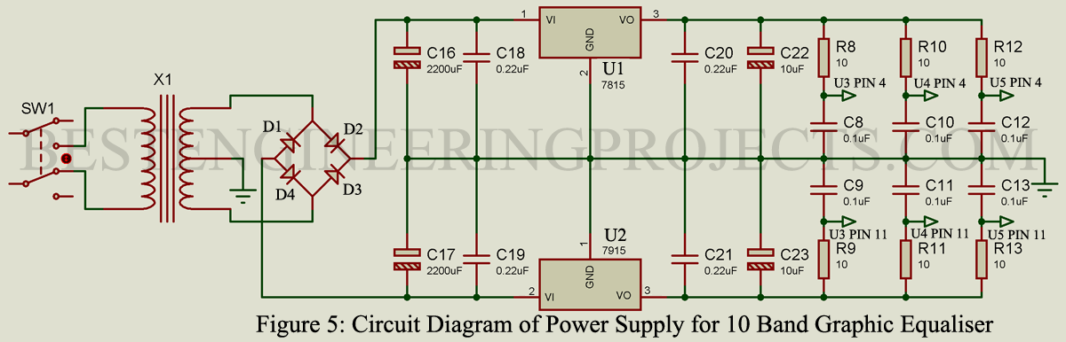
Power Supply Circuit
The power supply required for this circuit is +15V and -15V, this can be achieved by using a fixed voltage regulator IC. 220V/50Hz or 110V/60Hz is given to the primary side of transformer X1 through a DPDT switch as shown in the circuit of the power supply. The secondary side is connected to a bridge rectifier built using four rectifier diodes. Pulsating DC is filtered using a capacitor network built using capacitors C16 to C19. This filtered output is further given to the fixed voltage regulator IC. The output +15V and -15V is further passed through the capacitor network built using capacitor C20 to C23. While selecting a capacitor for the power supply, try to use a polyester capacitor for 0.22µF capacitors (i.e. C18 to C21). The power supply is given to the IC through the RC network as shown in the circuit of the power supply. This is done to decouple the power supply from the IC.
Component used in 10 Band Graphic Equalizer Circuit
| Resistor (all ¼-watt, ± 5% Carbon) |
| R1, R3 = 100KΩ
R2 = 22KΩ R4 = 5.6KΩ R5 – R14 = 100KΩ R15 – R24 = 470Ω R25 = 5.6KΩ VR1 – VR10 = 22KΩ Log. potentiometer |
| Capacitors |
| C1, C18-C21 = 0.22µF (Polyester Capacitor)
C2, C3 = 220pF (Styroflex Capacitor) C4-C7 = refer Table II C8 – C13 = 0.1 µF (Ceramic Disc Capacitor) C14, C15, C22, C23 = 10µF/25V (Electrolytic Capacitor) C16, C17 = 2200µF/35V (Electrolytic Capacitor) |
| Semiconductors |
| U1 = LM7815, 15V Positive fix voltage regulator
U2 = LM7919, 15V Negative fix voltage regulator U3, U4, U5 = TL084 or TL074 Bi-FET quad op-amp D1 – D4 = 1N4002, 1-amp rectifier diode |
| Miscellaneous |
| X1 = 18V-0-18V, 250mA secondary transformer
SW1 = DPDT toggle switch Knobs for variable resistor Shielded wire
Check out other top popular Articles : |