The DIY project posted here is of Opto Reflective Sensor using 555 IC and TCRT5000 module. These sensors are photoelectric sensors, which signifies that they rely on photo or light and do not need to be in contact with any other objects to sense. When a beam of light between the reflector and light sensor is interfered, that is when the sensor sends electrical signals. These electrical alerts are the information to the output unit. These days opto reflective sensor is used in various projects like proximity sensing, position detector, robotics etc. Getting along, we have posted a DIY project with a working range of 2mm to 10mm.
But before that, let’s see what an opto reflective sensor can be used for. It is commonly used to detect reflective objects: their presence or absence. Like, it can be used to detect the presence of an obstacle along the way. It can also determine the distance from the entities.
The module used here is TCRT5000 which have an infrared LED and a photo transistor fabricated internally. We can often see the TCRT5000 on a board integrated with a voltage comparator chip like LM393 and an adjustable potentiometer alongside. The main advantage of using this module is its high-sensitivity as both the transmitter and receiver are positioned in the same unit and gives both analog and digital output.
Analog Output: When the module TCRT5000 get reflected IR rays, then the output rises from 0V to 3V DC. According to the intensity of IR rays falling on it, the output achieved is analog in nature.
Digital Output: Similarly, when the module TCRT5000 get reflected IR rays then the output rise to logic high (1) from logic low (0) and is digital in nature.
Circuit Description of DIY Opto Reflective Sensor using 555
The circuit of DIY opto reflective sensor using 555 is shown in figure 1 and is built around timer IC 555 and an opto reflector sensor module TCRT5000. Timer IC 555 is configured in monostable multivibrator mode which gets trigger from TCRT5000 module. For current limiting of IR, LED is fabricated internally to TCRT5000 module and a 470Ω (R1) is connected as shown in circuit diagram.
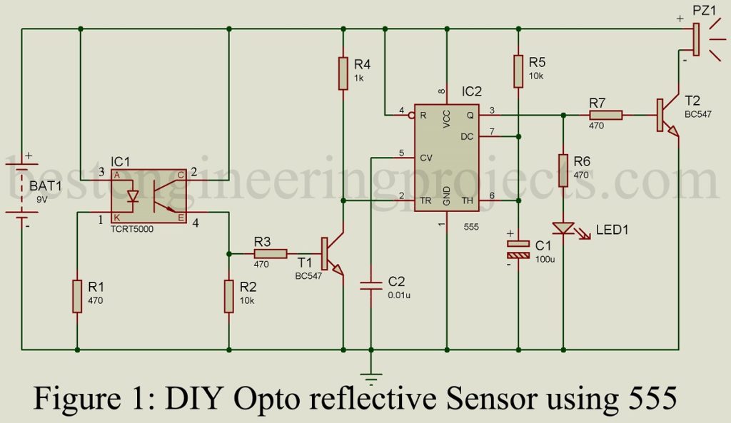
Initially, (i.e. no IR rays detected by module) the trigger pin of IC 555 is high as result output of IC 555 is low. But when IR rays are detected by the module, the internal phototransistor starts to conduct which induces transistor T1 to start conducting. Now, the collector voltage of transistor T1 goes low, which forces trigger pin of IC 555 to go low. The low voltage at trigger pin (pin 2) of IC1 makes output high for 1 second. The high output makes LED1 glow and drive transistor T2 in conducting state which further makes piezo buzzer to generate sound. The audio and visual indication (LED and piezo buzzer) indicates that opto reflector sensor module receives IR rays.
NOTE: Although sensor module has casing for filter false triggering but sunlight can trigger the circuit. So, testing of circuit must be done inside a room where only artificial light is available.
More interesting DIY Projects posted in bestengineeringprojetcs.com
- DIY Li-Fi Speaker | How to Design
- DIY Distance Measurement using GPS and ATmega328P
- DIY Soccer Substitution Board using AT89C51
- DIY Breathalyzer using Arduino and MQ-3 Sensor Module
- DIY Digital Compass using ATmega8
Component List
| Resistors (all ¼-watt, ± 5% Carbon) |
| R1, R3, R6, R7 = 470 Ω
R2, R5 = 10 KΩ R4 = 1 KΩ |
| Capacitors |
| C1 = 100 µF, 25V (Electrolytic Capacitor)
C2 = 0.01 µF (Ceramic Disc) |
| Semiconductor |
| IC1 = TCRT5000 (Opto reflective sensor module)
IC2 = NE555 (Timer IC) T1, T2 = BC547 (NPN Transistor) LED1 = 5mm any color LED |
| Miscellaneous |
| 9V battery
4-pin connector for IC1 |