Whenever we thought about distance measurement, an image of a circuit designed using an ultrasonic sensor is formed in our minds. But today we are going to present here a distance measurement project using the GPS (Global Positioning Measurement) module. The project named DIY Distance Measurement uses GPS and ATmega328 which measure the distance between two positions using the haversine formula.
The start point is the position where switch SW1 (Reading Switch) is pressed and the endpoint is the position when switch SW2 is pressed (Switch Switch). Thus, the circuit posted here will measure the distance between these two points (distance between SW1 button pressed and SW2 button pressed).
Circuit Description DIY Distance Measurement using GPS and ATmega328P
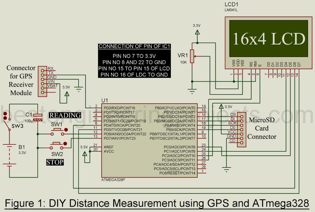
The circuit of DIY Distance Measurement using GPS and ATmega328P is shown in figure 1. The circuit is designed using an ATmega328 (8-bit microcontroller), a D2523T GPS receiver module, a microSD card, and a 16X4 LCD module.
ATmega328
Atmega328 is an 8-bit low-power CMOS microcontroller produced by Atmel. Its architecture is based on AVR enhanced RISC architecture. It is equipped with 32KB in-system flash memory, 1KB EEPROM, and 2KB internal SRAM which is enough for our project. The operation voltage is about 1.8V to 5.5V, here in this project we are using a 3.3V battery for operation. As it has the features of power-on reset, we are not using external reset circuitry. We are also using an internal calibrated oscillator rather than an external clock oscillator for less power consumption.
D2523T GPS Receiver Module
The D2523T GPS receiver module is equipped with saranted GeoHelix high gain with an update rate of 4Hz. This module is operating on 3.3V DC and has URAT (TTL) interface. It has a sensitivity of 160dBm and is omnidirectional @ typical gain of +26dBic. The GPS receiver module has a green led used to indicate pulse per second (PPS). The latitude and longitude are with date and time are shown in LCD.
16X4 LCD Module
In the project DIY Distance Measurement, we had used 16X4 alphanumeric LCD for display output. The LCD is designed to display the alphabet, numbers, or even special characters. This LCD has four rows and each row displays 16 characters. It can operate either in 4-bit mode or in 8-bit mode. Here, we are using it in 4-bit mode as only four data lines are connected to the microcontroller (shown in figure 1).
Memory Card Module
For storing longitude, latitude, date, time, the distance measured, etc. we had used a MicroSD card. The card can be of 8 Gb or 16 Gb or any capacity for storing purposes.
Working on the DIY Distance Measurement using GPS and ATmega328P
Initially, switch SW3 is open, but when SW3 is closed the circuit start to work with the initialization of the GPS receiver module. It took approx. 20 seconds to stable and read the latitude and longitude of that position. The green led attached to the D2523T GPS module indicates that the GPS module is ready to use. When the user presses switch SW1 the initial position is marked and it starts to measure up to the final position. The final position is the location where switch SW2 is pressed.
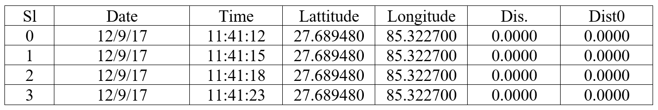
All the data like serial no. date, time, longitude, latitude, total distance, etc. is displayed in the LCD module. These data are further processed and stored in MicroSD card in .txt format. This stored data can be used in the future for research purposes. For accuracy, we are taking locations up to 6 decimal points to calculate distance.
For better understanding and visually we had created a scenario on how to measure the distance of different positions. Let’s assume an initial position X and a final position Z where position Y is an intermediate location. Now, we are going to measure the distance between X and Z through Y. To measure distance, we had to press switch SW1 till the final point. We first press switch SW1 (reading switch) at position X and keep it pressing till we had reached position Y. When we reach to position Y, switch SW1 is released as a result display starts to flash information (i.e. Distance/Total distance). Let the distance between X and Y be 50M then it shows 50/50 in the third row of LCD. Now again SW1 is pressed till we reach the final position (Z). When we reach position Z switch SW1 is released, as a result, the display starts to flash the Distance/Total Distance. Let the distance between Y and Z be 100M then it shows 100/50. When switch SW2 is pressed, it terminates the program and closes the file. Thus, from the above scenario, we conclude that SW1 is for measuring lap whereas SW2 is for total distance.
Whenever the user starts the device, a new log file is created with the following data and format as shown below. The table shown below is just for batter visualization, in a real log file there is notable.
Software for DIY Distance Measurement using GPS and ATmega328P
Software for DIY Distance Measurement Using GPS and ATmega328 is written in Arduino programming language and compiled using Arduino IDE. You can directly download the folder from the link given below. The folder contains Software code in Arduino programming language and the necessary library file.
Click Here to Download Software Code
PARTS LIST OF DIY DISTANCE MEASUREMENT USING GPS AND ATMEGA328
| Resistors (all ¼-watt, ± 5% Carbon) |
| VR1 = 10 KΩ |
| Capacitor |
| C1 = 10 µF/16V (electrolytic capacitor) |
| Semiconductor |
| IC1 = ATmega328P |
| Miscellaneous |
| D2523T GPS Receiver Module
16X4 LCD Module MicroSD Card with adapter SW1, SW2 = Push-to-on switch SW3 = ON/OFF switch B1 = 3.3V Li-Po battery or equivalent |
Other project-based on GPS posted in bestengineeringprojects.com
- GPS Module Interface with ATmega16
- GPS Navigator Circuit using ATmega 16
- GPS and GSM based Vehicle Tracking System
- Accident Detection and Alert System using Arduino