The project “IC 555 based Automatic Evening Lamp” is simple and built around timer IC 555 and LDR. The bulb used in the circuit is turned on automatically in low light (evening) and turned off in the morning.
Various other automatic night lamp circuit is already posted on betsengineeringprojects.com. Some are listed here, Automatic Night Lamp Circuit using TRIAC and SCR, Automatic night lamp using 7486 IC, Light Sensor Switch Circuit using LDR, and 741 IC. The circuit posted here is a standalone automatic evening lamp; simply you have to connect to the mains supply and place where you want to use it.
Circuit Description of Automatic Evening Lamp
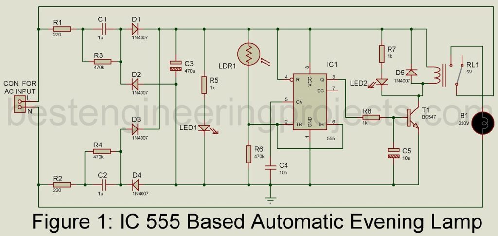
The circuit of the IC 555 Based Automatic evening lamp is shown in figure 1. The circuit is designed using readily available components like timer IC 555, an LDR, and a few other electronic components like resistors, capacitors, diode, transistor, etc. For description, we divide the entire circuit of IC 555 Based Automatic evening lamp into three main sections i.e. power supply, control unit, and switching unit.
Power Supply Unit | IC 555 Based Automatic evening lamp
The power supply unit is designed using resistors, capacitors, and diodes as shown in the circuit diagram. Here we are using a capacitor and resistor for voltage drop rather than a conventional transformer. The use of a transformer makes the circuit bulky and expensive. The two capacitors C1 and C2 used in this circuit are used to drop the mains voltage up to the desired level where resistors R1 and R2 is used as current limiter which protects the circuit from instant high current. Resistors R3 and R4 are connected parallel to capacitors C1 and C2 respectively, the function of these resistors is to discharge the capacitor when power is off. The resistor prevents shock due to energy stored in a capacitor.
The low voltage output of capacitors C1 and C2 further need to change to DC voltage. For changing AC to DC we had used a bridge rectifier built around four general-purpose rectifier diodes (1N4007). This rectified output is filtered using capacitor C3 to make ripple-free DC output. The working status of the power supply unit is indicated by LED1 where a resistor R5 is a current limiter resistor that protects the LED from burning out.
Control Unit | IC 555 Based Automatic evening lamp
The control unit of the IC 555 Based Automatic evening lamp is designed using timer IC 555 and LDR. The timer IC 555 is configured in bi-stable mode. The trigger pin (pin 2) and threshold pin (pin 6) is stored which is further connected to the output of LDR as shown in the circuit diagram. You can also adjust the sensitivity of LDR by replacing R6 with a 1M variable resistor. The threshold and trigger of IC1 are controlled by LDR and a 470 (R6) resistor.
When LDR1 offers low resistance (Day time) the threshold of IC 555 becomes high as a reset the internal flipflop reset and output become low. Similarly, when LDR1 offers high resistance the threshold of IC 555 becomes low as a result the internal flip fop sets and output become high. The output of IC1 is available at pin 3.
Switching Circuit | IC 555 Based Automatic evening lamp
The switching circuit is designed using a 5V relay and a transmitter. When the output of IC1 is high transmitter T1 starts to conduct as a result the relay energized. The energized relay RL1 switch on the Bulb B1 till the resistor of LDR becomes low. Similarly, when the output of IC1 becomes low, transistor T1 goes into the cut-off region as a result the relay connected to collects is de-energized, and Bulb B1 gets switched off.
PCB Design:
PCB diagram is designed using Proteus 8.1 design suite. The actual size solder side PCB and component side PCB diagram are shown in the figure below. Click the link below to download the PCB diagram in PDF format.
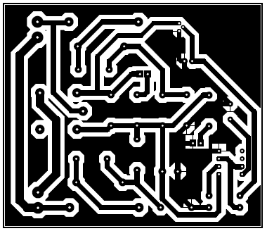 Figure 2: Solder Side PCB
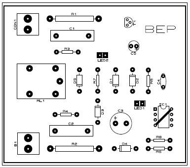
Figure 3: Component side PCB
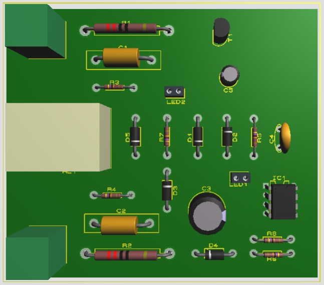
Figure 4: 3D view of Automatic Evening Lamp
PARTS LIST OF IC 555 BASED AUTOMATIC EVENING LAMP
| Resistors (all ¼-watt, ± 5% Carbon) |
| R1, R2 = 220 Ω, 1W
R3, R4, R6 = 470 KΩ R5, R7, R8 = 1 KΩ |
| Capacitors |
| C1, C2 = 1 µF, 400V (Polypropylene Film Capacitor)
C3 = 470 µF, 16V (Electrolytic Capacitor) C4 = 10nF (Ceramic Capacitor) C5 = 10 µF,16V (Electrolytic Capacitor) |
| Semiconductors |
| IC1 = NE555 (Timer IC)
T1 = BC547 (NPN Transistor) D1 – D5 = 1N4007 (General Purpose Rectifier Diode) LED1, LED2 = 5mm any color LED |
| Miscellaneous |
| RL1 = 5V Relay
B1 = 230V, 60W AC bulb LDR1 = Light Dependent Resistor |