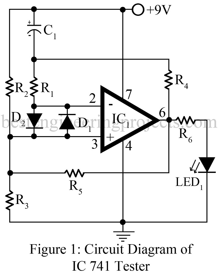
The op-amp IC 741 is a DC-coupled, high gain differential amplifier with external negative feedback. IC 741 is characterized by the almost infinite open-loop gain (100,000), almost infinite input impedance (2MΩ), and almost zero output impedance (75Ω). IC 741 is the most popular, cheap, and easy-to-use op-amp. Various type of circuit is designed using Op-amp 741 out of which some are voltage follower, current to voltage converter and vice versa, summing amplifier, etc.
Various type of circuit based on op-amp 741 is already posted in bestengineeringprojects.com on the op-amp section. Now here is a simple circuit operational amplifier 741 tester which test op-amp 741 either is good or fault.
Circuit Description of Operational Amplifier 741 Tester
The circuit of the operational amplifier 741 tester comprises two diode and very few passive components and a 741 IC to be tested. All the components are connected as shown in the circuit diagram. An LED1 is used to indicate whether IC is good or fault. Blinking LED1 indicates IC is good.

Working of the circuit | Operational Amplifier 741 Tester
The working of the circuit is simple. The IC to be tested is configured in voltage comparator mode. The voltage at pin 3 (noninverting pin) is fixed whereas the voltage at pin 2 (inverting pin) varies due to the charging and discharging of capacitor C1. Where the battery is connected to the circuit the voltage at pin 3 is high compared to the voltage at pin 2 due to the charging of the capacitor, as a result, the output of IC becomes high, and the LED starts to glow.
At this instant capacitor start to charge through the resistor R4. When the charge (voltage) of the capacitor exceeds the voltage at inverting pin (pin 2), the output of IC becomes LOW, as a result, the LED stops glowing. When the voltage at the capacitor becomes higher than inverting input pin it starts to discharge and again the output of IC becomes high. This high and low output of IC generates a square wave and causes LEDs to blink.
NOTE: If the LED doesn’t blink in a fixed interval of time i.e. either stay ON or OFF, the IC which is testing is faulty.
Check out other various electronic component tester circuits posted in bestengineeringprojects.com
- RJ45 Cable Tester Circuit
- Zener Diode Tester Circuit
- Relay Tester Circuit
- Capacitor Tester cum Flasher
- 555 Timer IC Tester
PARTS LIST OF OPERATIONAL AMPLIFIER TESTER
|
Resistor (all ¼-watt, ± 5% Carbon) |
|
R1 – R4 = 10 KΩ R5 = 4.7 KΩ R6 = 1 KΩ |
Capacitor |
|
C1 = 10 µF/16V (Electrolytic Capacitor) |
Semiconductors |
|
IC1 = 741 (IC to be test) D1, D2= 1N4007 or 1N3002 LED1 = Any Color LED |
this project is not working
this project is 100% verified and working. Please go through video.
So, op-amp in this video is damaged? Because it’s blinking instead of glowing. Right?
Sorry, i have edited, blinking if LED1 indicate IC is good to work. As the above circuit is configured in oscillator which generate frequency thus LED blink instead glow.
OP-amp used in video is good.
Can I use 1N4148 for the diode?
sir,i hve selected Ic741 Tester as my miniproject.Now i have to make report(ppt) on this.
Sir,i would like to hear ur views on headings/points/(also subpoints) for the report.
Thankyou!
Will it work with +5V???
Might work with little modification.
What is the purpose of the 2 diodes?
Hello,
Ilike the project very much, and would like to know if I can replace 1N4007 with 1N4148.
I build the circuit but only get a glowing led, no matter if I’m testing a new 741 or and old and probably broken one.
Is there some tests I can do to verify if it is working ?
Thanks for you time
Pierluigi