Here is the relay tester circuit using timer IC 555 which is used to measure pull-in and release voltage of relays ranging from 6V to 28V DC. Relays are probably the simplest electromechanical devices, yet they are the most important components of many industrial and domestic electrical equipment.
All too often, it is a hardship for the equipment manufacturers to discover that the commercial quality relays of similar types have a wide range of operating voltage. Many times, it is found that the relay contacts will not close properly. Many electrical shock hazards are traced back to the unintentional shorts that exist because of the contacts of the relays and their yokes which make contact with the metal cabinets of the equipment.
Here is a relay tester circuit that can be used to:
- Measure the exact ‘pull-in’ and ‘release’ voltage of relays of normal voltages ranging from 6V to 28V DC.
- Select the relays which operate in the desired voltage range. This is a GO-ON-GO check.
- Check the relay contacts in both the energized and released conditions. Any short between the yoke and any of the contacts is also indicated. This is also a GO-NO-GO check.
Circuit Description and Working of Relay Tester Circuit
The relay tester circuit (figure 1) consists of a variable power supply using a series power transistor 2N3055 and the voltage regulator IC 723 in a simple feedback arrangement. Potentiometer VR2 is used to vary the output voltage continuously from 3.5V to 28V. Resistors R4 and R5 divide the 7V reference voltage of the IC and provide the non-inverting input with a voltage of 3.5V.
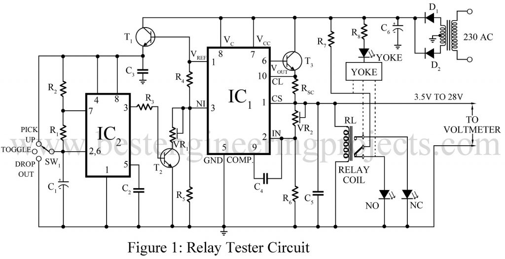
Transistor T2 switches potentiometer VR1 out of the circuit or places it in parallel with resistor R5. Transistor T1 buffers the reference voltage output and energizes the astable built around IC2 (555).
Resistor Rsc limits the output short circuit current to 150 mA. Connections to the contacts and the coil of the relay are made either by using the corresponding relay socket or by using alligator clips. Connection to the yoke is made via the screw provided for fixing the relay.
This relay tester circuit is very simple to use. The single-pole 3-position rotary switch SW1 is set to the ‘pick-up’ position and the potentiometer VR2 is adjusted to use the tester as a variable power supply for measuring the exact pull-in and release voltage of the relays.
To use the relay tester circuit to select the relays which operate in the desired voltage range:
- Set the switch to the ‘pick-up’ position and adjust VR2 to get a voltage across the relay coil equal to the desired ‘pull-in’ voltage as monitored in the voltmeter.
- Set the switch to the ‘drop-out’ position and adjust VR1 to get a voltage across the relay coil equal to the desired drop-out voltage.
- Set the switch to the ‘toggle’ position. The astable oscillates at 2 Hz and switches the voltage across the relay coil between the two-level set in procedures 1 and 2. If the relay operates in the set voltage range, the LEDs ‘NO’ and ‘NC’ indicate the changeover of the contacts.
LED ‘YOKE’ indicates the shorting, if any, between the yoke of the relay and its contacts.
Check out other various electronic component tester circuits posted on bestengineeringprojects.com
- RJ45 Cable Tester Circuit
- Zener Diode Tester Circuit
- 555 Timer IC Tester
- Capacitor Tester cum Flasher
- Operational Amplifier 741 Tester
PARTS LIST OF RELAY TESTER CIRCUIT
| Resistor (all ¼-watt, ± 5% Carbon) |
| R1 = 100 KΩ
R2, R3 = 1 KΩ R4, R5 = 2.2 KΩ R6 = 2.7 KΩ R7 = 5.6 KΩ R8 = 3.9 KΩ RSC = 5 Ω VR1, VR2 = 22 KΩ LIN. |
| Capacitors |
| C1 = 3.3 µF, 50V
C2 – C5 = 0.1 µF C6 = 220 µF, 50V |
| Semiconductors |
| IC1 = 723 CAN
IC2 = 555 T1 = SL100 T2 = BC148 T3 = 2N3055 D1, D2 = 1N4001 LED1 – LED3 = 3mm any LED |
| Miscellaneous |
| X1 = 230 V AC Primary 25-0-25V, 150 mA Secondary Transformer
SW1 = single pole 3 position switch RL1 = Relay as per desire |