The automatic submersible pump controller circuit posted here is used to automate the operation of an electrical submersible pump (ESP) based on the level of water in the overhead tank. The Automatic submersible pump controller circuit can be used as a standalone system and can be interfaced with the existing manual control panel.
Introduction to electrical submersible pump (ESP)
Electrical submersible pumps, often called ESP are single or multiple-stage radial flow pressure series impeller pumps that are closely coupled to the motor for low and medium heads. ESPs are efficient and reliable and thus find application in domestic, industrial, irrigation, air-conditioning, and various other systems. ESPs are used to lift moderate to high volumes of water/fluids from wellbores.
Classification of ESP
ESP are classified according to
- Bore diameter: The bore diameter generally varies from 100mm to 200mm.
- Horsepower: The horsepower generally varies from 0.5Hp to 40Hp.
- Discharge rate: The discharge rate typically varies from 120 liters per minute for 0.5Hp to about 2000 liters per minute for 40Hp.
- Power supply: For low and medium-range, one can use a 3-phase or split-phase (also referred to as a 2-phase) supply. But ESPs of 3HP or higher rating invariably use a 3-phase supply.
Working of ESP Motor
To know how this motor works, let us consider a split-phase motor of 1.5Hp with a bore diameter of 100mm. In running condition, the motor draws a current of about 10 to 11 amp, but at starting required current is around 2.5 to 3 times the value of the running current.
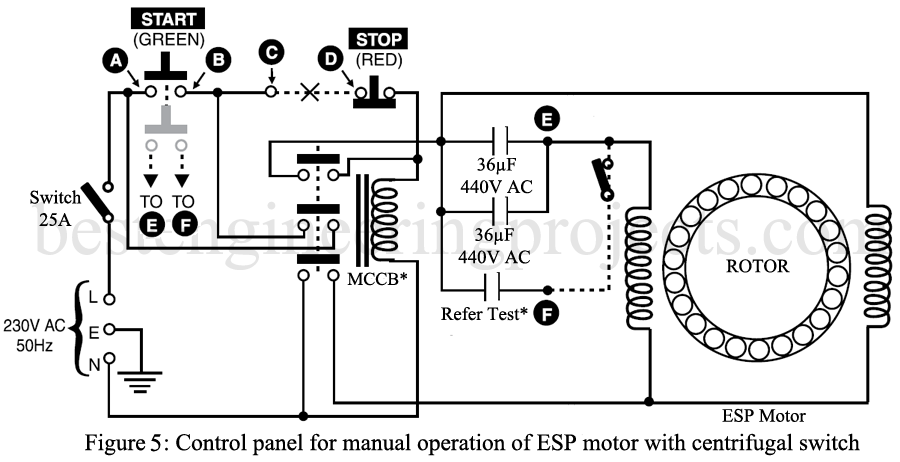
The start capacitor is 120-150µF, 230V AC bipolar paper electrolytic capacitor where the run capacitor is 72µF 440V AC capacitor (36µF || 36µF). These capacitors are connected in parallel through a centrifugal switch. This parallel combination of the start and the run capacitors is connected in series with the run winding of the motor. ESP motor achieved sufficient speed after two to three seconds of running. When the motor achieves its speed, the centrifugal switch will open and as a result, the start capacitor will be disconnected but the run capacitor stays in the circuit permanently. The value of the start capacitor and the run capacitor is dependent on the power of the motor. The value of the stat capacitor can be determined by table 1 where the value of the run capacitor can be calculated by adding 70µF per Hp of the motor.
Table 1: Value of Start Capacitor
| Motor rating in HP | Start capacitor value (µF) 230 AC (working) 275 AC (Surge) |
| 1/6 | 20-25 |
| 1/5 | 30-40 |
| 1/4 | 40-60 |
| 1/3 | 60-80 |
| 1/2 | 80-100 |
| 3/4 | 100-120 |
| 1 | 120-150 |
 |
150-200 |
| 2 | 200-250 |
Operation of ESP Motor Manually
The circuit for the manual operation of the ESP motor with the centrifugal switch is shown in figure 1. This circuit is built using an ON/OFF switch (Isolator type), a push-to-on dual section button (start switch), a push-to-off button (stop switch), a motor circuit protector with a magnetic trip and resetting facility, and a start and run capacitors. You can also add an ammeter, voltmeter, and neon indicator.
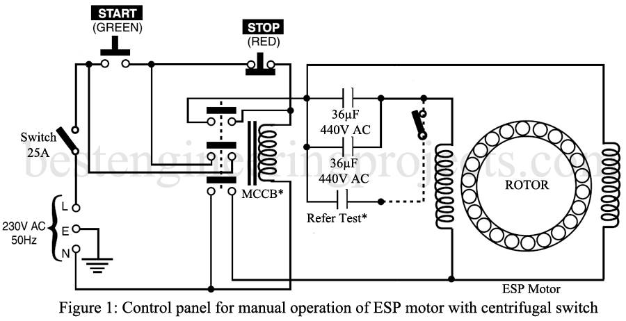
The start pushbutton is normally open whereas the stop pushbutton is normally closed. These two switches are connected in series with a live line or phase line. When the start button is pressed, the contractor of MCP energizes as the off switch is normally closed.
Out of three contact pairs, one contact pair of contractors is used to hold the contact to provide a parallel path to the contact coil even after the start switch is depressed. This hold contact provides a latch.
One contact pair provides a phase or live connection to the motor whereas other contact pairs provide neutral. When the motor gains around 80% of its speed, the centrifugal switch open as a result the start capacitor disconnect from the circuit. Where the run capacitor will stay in the circuit permanently.
When the stop switch is pressed, the supply will be interrupted and as a result, the motor will be stopped. In this way, the motor will start when the start switch is pressed and stop when the stop switch is pressed.
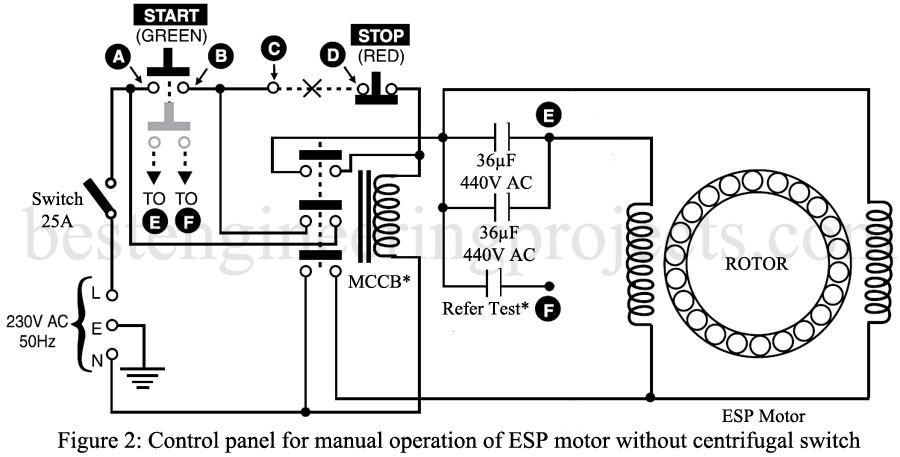
All the ESP motors do not consist of an internal centrifugal switch. In that case, the start switch works as a centrifugal switch. For that connect points A and B to points E and F as shown in figure 2. As the start switch does not have a holding facility, the start capacitor disconnects as soon as the start switch is released.
Circuit Description of Automatic Submersible Pump Controller Circuit
The Automatic submersible pump controller circuit is divided into two sections i.e. motor control section and the power supply section
Power supply section:
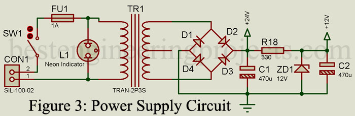
The circuit of the power supply is shown in figure 3. The main supply tapped from the same point from which it is fed to the control panel is connected to the primary side of transformer TR1 through an on/off switch and a fuse. Center-tap transformer TR1 step-down the ac mains voltage to 12V-0-12V. Here in this circuit, we are not utilizing the 0V terminal of the secondary side. The output of the transformer is rectified using a bridge rectifier utilizing four general-purpose rectifier diodes D1 to D4 which is further filtered using a 470µF capacitor. 24V DC for relay RL1 and RL2 is available across capacitor C1. Except for relay RL1 and RL2, the circuit works on a 12V regulated power supply. Zener diode ZD1 regulates the 24V power supply to 12V. This 12V is obtained across capacitor C2
Motor Control Circuit:
The circuit of the Automatic submersible pump controller circuit is shown in figure 4. +12V is given to a common probe through a current limiting resistor and a diode D9. The low-level probe is connected to the input of inverter gate U1:C through a voltage divider network built using resistors R9 and R10, which further pass through inverter gates U1:D and U1:E. The output of U1:E is given to the base of transistor T2 through a diode D6 and current limiting resistor R11. The high-level probe is connected to the input of inverter gate U1:A through a voltage divider network built using resistors R7 and R8. The output of the inverter gate is U1:A passes through another inverter gate U1:B and is further given to the base of transistor T1 through diode D5 and current limiting resistor R6.
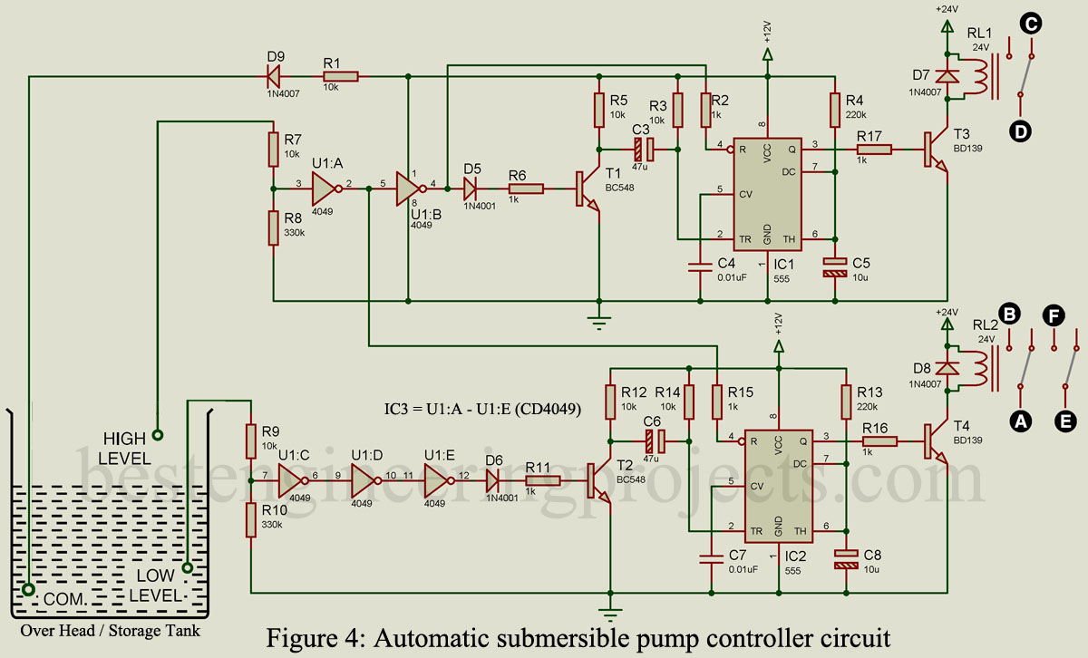
Both timers IC (IC1 and IC2) are configured in monostable mode or timer mode. The RC component is selected such that the output pulse width will be 2.5 to 3 seconds i.e. output will be high for 2.5 to 3 seconds. Timer IC1 and timer IC2 will be triggered through transistors T1 and T2. To protect the circuit from false triggering the reset pin of the timer, IC is connected to the output of the inverter gate. The reset pin of IC1 and IC2 is connected to the output pin of inverter gate U1:B (pin 4) and U1:A (pin 2) respectively. This also ensures that these two relays never operate simultaneously.
The output of timer IC1 and timer IC2 is given to the base of transistors T3 and T4 respectively to drive the stop relay and start relay. A diode is connected across the relay in reverse bias mode to protect the circuit from flyback emf.
Sensor probe: For the sensor, use stainless steel rods or bob and screw with telephone-type 25/25 SWG wire for connection to the circuit. Cover the joint with epoxy.
Interfacing Automatic Control Circuit with Manual Control
Connect all the circled points of the manual control unit to the circled points of the automatic control unit. i.e. A, B, C, and D of the automatic control unit must be connected to circled points A, B, C, and D of manual control respectively. Points E and F will be connected only if the motor does not have an integral centrifugal switch. Point C and point D in the manual control unit is framed by disconnecting one of the wires going to the off button terminal i.e. in series with the off button as shown in figure 5.
Operation of the Automatic Submersible Pump Controller Circuit
The operation of the circuit is explained using a truth table for relay operation
Table 2: Truth Table for Relay Operation
| The water level in the tank | Stop relay operation (RL1) | Start relay operation (RL2) | Pump motor operation |
| Below low level | No | Yes | Starts |
| Above low level and below high level | No | No | Remains on |
| Reaches high level | Yes | No | Stops |
When the water of the overhead tank is below the low level, the input of inverter gates U1:C and U1:A will be below as a result output of these gates will be high. This causes high output at the base of transistor T2 and low at the base of transistor T1. This triggers IC2 which further triggers the start relay RL2 for 2.5 to 3 seconds and as a result, the motor starts. When the water level increases above a low level but below a high level, no relay will be energized but the motor remains in ON condition.
When the water level reaches a high level, the input of inverter gate U1:A will be high as a result output becomes low. This low output of U1:A reset timer IC2 and trigger timer IC1. The output of the timer IC1 will be high for 2.5 to 3 seconds, further energized stop relay for 2.5 to 3 seconds, and the motor will stop.
Check out other water level indicators and controller circuit
- Ultrasonic water level meter
- Water Level Indicator Circuit using 7-Segment
- Water Level Indicator Circuit
- Water Level Controller Using NE555
PCB Diagram of Automatic Submersible Pump Controller Circuit:
PCB Diagram of Automatic submersible pump controller circuit is designed using Altium design. Solder side and component side PCB are shown in Figures 6 and 7 respectively whereas the 3D design is shown in figure 8. Download the actual size solder side and component side PCB in PDF format from the link below.
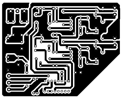
Figure 6: Solder Side PCB
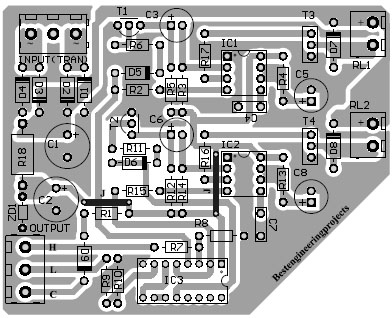
Figure 7: Component Side PCB

Figure 8: 3D View of Automatic submersible pump controller circuit
Click here to download the PCB
Component list of Automatic Submersible Pump Controller Circuit
| Resistor (all ¼-watt, ± 5% Carbon) |
| R1, R3, R5, R7, R9, R12, R14 = 10KΩ
R2, R6, R11, R15 – R17 = 1KΩ R4, R13 = 220KΩ R8, R10 = 330KΩ R18 = 330Ω, 1W |
| Capacitors |
| C1 = 470µF, 63V electrolytic capacitor
C2 = 470µF, 25V electrolytic capacitor C3, C6 = 47µF, 25V electrolytic capacitor C4, C7 = 0.01µF ceramic disc C5, C8 = 10µF, 25V electrolytic capacitors |
| Semiconductors |
| IC1, IC2 = NE555 Timer IC
IC3 = CD4049 hex inverter/buffer T1, T2 = BC548 NPN general purpose transistor T3, T4 = BD139 NPN power transistor D1 – D4, D7 – D9 = 1N4007 rectifier diode D5, D6 = 1N4001 rectifier diode ZD1 = 12V, 1W zener diode |
| Miscellaneous |
| TR1 = 230V AC primary to 12V-0-12V, 1 amp. Secondary transformer
L1 = Neon bulb with inbuilt resistor SW1 = On/off switch FU1 = 1 amp. fuse RL1 = 24V, 250Ω, 1 c/o relay, 30A contact rating RL2 = 24V, 250Ω, 2 c/o relay, 30A contact rating |
It,s an amazing circuit. But if it had water level indicator LEDs like TanK Full, Tank Empty, PUMP On indicator, Dry Run sensor It may be the best project.. Again thanks a lot… Have a good day..
dry run sensor is not found in the circuit.