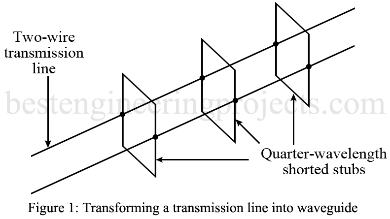
A rigorous mathematical demonstration of waveguide operation is beyond our intentions. A practical explanation of waveguide operation is possible by starting out with a normal two-wire transmission line. If an infinite number of these supports were added both above and below the two-wire transmission line as shown in Figure 1, you can visualize it turning into a rectangular waveguide.
Waveguide Operation
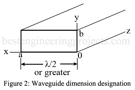
If the shorted stubs were less than a quarter wavelength, the operation would be drastically impaired. The same is true of a rectangular waveguide. The a dimension of a waveguide, shown in Figure 2, must be at least one-half wavelength at the operating frequency, and the b dimension is normally about one-half the a dimension.
The wave that is propagated by a waveguide is electromagnetic and, therefore, has electric (E field) and magnetic (H field) components. The configuration of these two fields determines the mode of operation. If no component of the E field is in the direction of propagation, we say that it is the TE mode. TE is the abbreviation for transverse electric. TM is the mode of waveguide operation whereby the magnetic field has no component in the direction of propagation.
Two-number subscripts normally follow the TE or TM designations, and they can be interpreted as follows: For TE modes, the first subscript is the number of one-half-wavelength E-field patterns along the a (longest) dimension, and the second subscript is the number of one-half-wavelength E-field patterns along the b dimension.
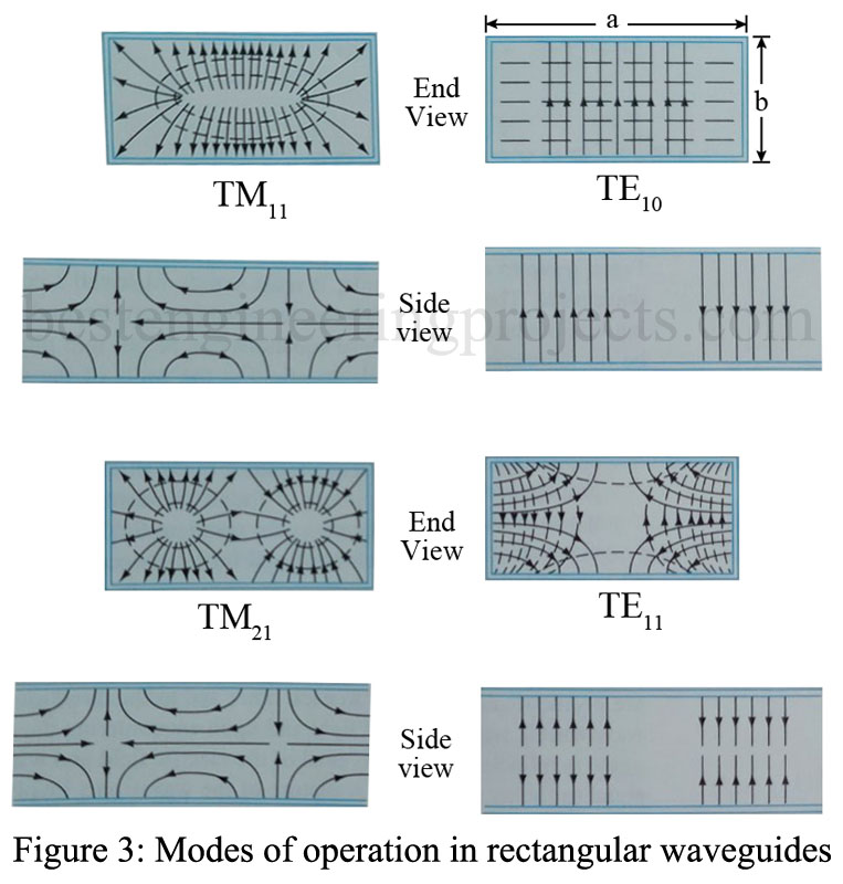
For TM modes, the number of H fields along the a and b dimensions determines the subscripts. Refer to Figure 3 for further illustration of this process.
The electric field is shown with solid lines and the magnetic field with dashed lines. Notice the end view for the TE10 mode in Figure 3. The electric field goes from a minimum at the ends along the a dimension to a maximum at the center. This is equivalent to one-half wavelength of E field along the a dimension, while no component exists along the b dimension. This is, therefore, called the TE10 mode of operation. In the TM21 mode of operation note that along the a dimension the H field (dashed lines) goes from zero to maximum to zero. That’s two half wavelengths, while along the b dimension one-half wavelength of the H field occurs-thus the TM21 designation. Note that in the side views the H fields (dashed lines) are not shown for the sake of simplicity. In these side views the TE modes have no E field in the direction of propagation (right to left or left to right), while in the TM modes the E field (solid lines) does exist in the propagation direction.
Dominant Mode of Operation
The TE10 mode of operation is called the dominant mode because it is the most “natural” one for operation. A waveguide is often thought of as a high-pass filter because only very high frequencies can be propagated. The TE10 mode has the lowest cutoff frequency of any of the possible modes of propagation, including both TM and TE types. It is of special interest because there will exist a frequency range between its cutoff frequency of the lowest frequency that a given waveguide will propagate) and that of the next higher-order mode in which this is the only possible mode of transmission. Thus, if a waveguide is excited within this frequency range, energy propagation must take place in the dominant mode, regardless of the way in which the guide is excited. Control of the mode of operation is important in any practical transmission system, and thus the TE10 mode has a distinct advantage over the other possible modes in a rectangular waveguide. Even more important, however, is the fact that TE10 operation allows use of the physically smallest waveguide for a given frequency of operation.
The dimensions for an RG-52/U waveguide are 0.9 x 0.4 in. This is one of the standard sizes used in the X-band frequency range and is usually called the X-band waveguide. The recommended frequency range for this waveguide size is 8.2 to 12.4 GHz. As a result of this limited range of usefulness, standard sizes of waveguides have been established, each having a specified frequency range. These can be found in almost any modern handbook of electronic engineering. The formula for cutoff wavelength is
 ….(1)
….(1)
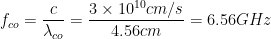
for the TE10 mode, where a is the long dimension of the waveguide rectangle. Thus, for an RG-52/U waveguide,  is 1.8 in, or 4.56 cm. Therefore,
 …..(2)
The lowest frequency of propagation (without considerable attenuation) is 6.56 GHz, but the recommended range is 8.2 to 12.4 GHz. The next higher-order mode is the TE20, which has a cutoff frequency of 13.1 GHz. Thus, within the frequency range from 6.56 to 13.1 GHz, only the TE10 mode can propagate within the X-band waveguide, in the ordinary sense of the word.