Wireless Ultrasonic Water Level Meter using ATmega328
Water level indicator is one of the most popular projects over the internet but the problem with that is, it uses metal electrodes as a result corrosion is occurring. When we pass DC in water it starts to react with the metal in presence of oxygen and corrosion is occurring.
This problem is minimized by using alternating current instead of direct current but there is always the risk of electric shock which can be dangerous if is handled by a non-technical person. By keeping this problem in mind, we had designed an ultrasonic water level meter that utilizes a wireless approach. Thus, there are no problems with corrosion, no more messy wires, and the receiver can be placed anywhere the user found easy.
The circuit of the Ultrasonic Water Level Meter presented below surmount the above flaw and displays the water level in a 16×4 alphanumeric display for better visual effect. The project posted here is capable to measure the depth of water up to 4 meters with an accuracy of 5mm.
Other Water level indicators and controller circuits posted in bestengineeringprojects.com
- Water Level Indicator Circuit using 7-Segment
- Water Level Indicator Circuit
- Water Level Controller Using NE555
Circuit Description of Ultrasonic Water Level Meter
Talking about the construction of the “Ultrasonic Water Level Meter” it uses a microcontroller for processing. ATmega328 is an 8-bit microcontroller, ultrasonic sensor, and 433 MHz RF module. As the project Ultrasonic Water Level Meter uses wireless approach it uses transmitter and receiver unit.
Transmitter Unit of Ultrasonic Water Level Meter
The transmitter circuit is shown in figure 1. The entire circuit of the transmitter is built around an 8-bit microcontroller ATmega328, ultrasonic sensor, 433 MHz RF transmitter module, and a few other electronic components like resistors, capacitors, etc. for working flawlessly.
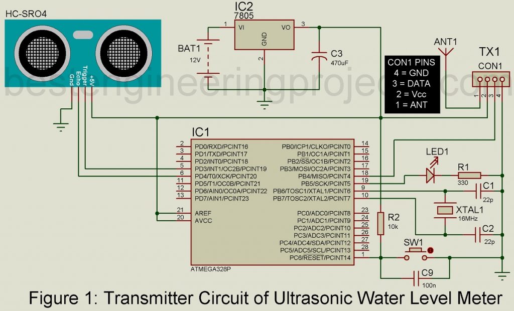
Port D of ATmega328 is used to communicate with ultrasonic sensors. Trigger pin and echo pin of ultrasonic is connected to PD3 and PD4 (pin 5 and 6) of ATmega 328 respectively. Port B is used to communicate with a 433 MHz RF transmitter module. DATA pin of 433 MHz transmitter module is connected to pin PB4 (pin 19) of ATmega328 as shown in the circuit diagram. A spiral antenna is used here to increase the transmitter range of the RF module.
Receiver Unit of Ultrasonic Water Level Meter
The receiver circuit of the Ultrasonic Water Level Meter is shown in figure 2. The entire circuit of the receiver is built around an 8-bit microcontroller. ATmega 328, 16×4 LCD module, 433 MHz RF receiver, and a few other electronic components like resistors, capacitors, etc. for working flawlessly.
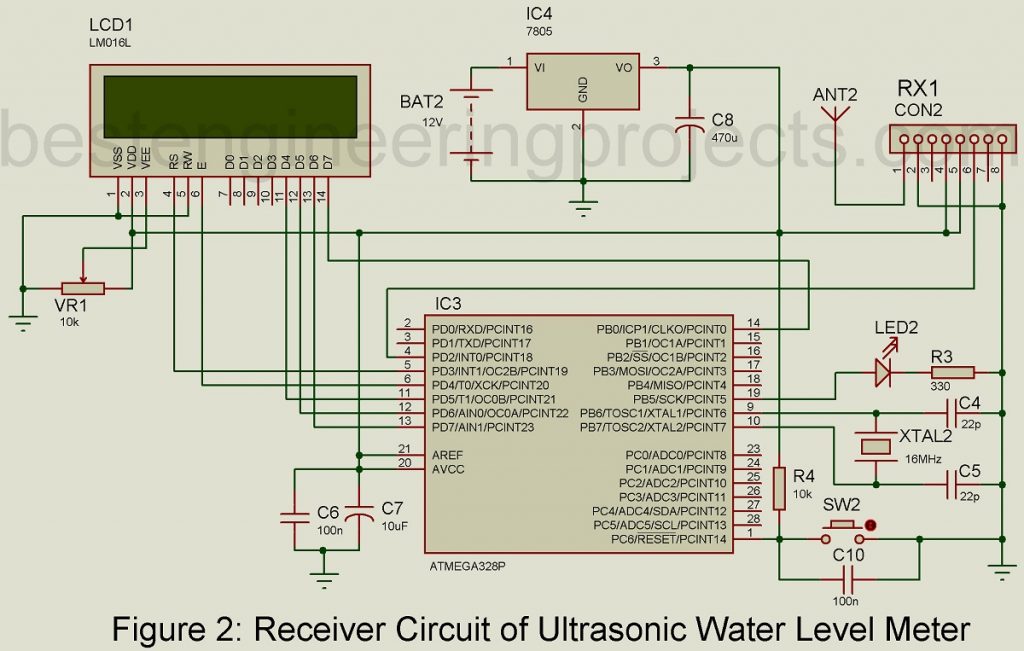
A 16×4 LCD module is used in this project to display results. Port D is dedicated for LCD and is configured in 4-bit mode by connecting higher bit data line of LCD (pin 11, 12, 13, and 14) to port PD5, PD6, PD7, and PB0 (i.e. pin 11, 12, 13, and 15) as shown in figure 2. Similarly, the E and RS pin of LCD is connected to pin 5 and 6 of microcontroller ATmega328. The RW pin of LCD is grounded to perform the write operation in LCD. Variable resistor VR1 is used to adjust the contrast of LCD. DATA pin of 433 MHz receiver module is connected to pin 4.
RESET Circuit of Ultrasonic Water Level Meter
ATmega328 is designed for power ON reset but sometimes we need an external reset circuit. The reset circuit for ATmega328 is designed using a 10K pull-up resistor, a switch, and a capacitor. The value of the capacitor is chosen such that it charges and makes the reset pin high for two machine cycles. The capacitor is connected in series to the resistor.
Power Supply Circuit of Ultrasonic Water Level Meter
The system is powered by two individual 12V battery supply i.e. one for the transmitter unit while the other for the receiver unit. As we all know that most of the electronics components work on 5V thus the input voltage is needed to convert. Thus, we had used a 5V series voltage regulator. A capacitor connected to the output is used to filter out the ripple if any available.
Working of the Circuit:
- Burn program on ATmega328 using Arduino bootloader and wire the entire circuit as shown in the diagram.
- Fix the ultrasonic sensor on the top of the tank says, in the middle of the cap of the tank.
- Connect the power supply to both units.
- LCD shows the level of the water tank with the accuracy of 5mm i.e. even a change of water level in CM LCD shows the result.
- For accuracy, the reading is taken 8 times a seconds and the average is shown in LCD.
- A counter is provided on the rightmost side of the LCD to show the transmitter circuit works properly and data is received.
- If the transmitter and receiver fail to work, LED1 and LED2 connected to pin 19 of the microcontroller stop blinking respectively.
Software: The software for ultrasonic water level meter is written in Arduino programming language and compiled using Arduino IDE. Click the link below to download the software. The folder contains software code for the transmitter, receiver, and the required library file.
CLICK HERE TO DOWNLOAD SOFTWARE
PARTS LIST OF ULTRASONIC WATER LEVEL METER
| Resistors (all ¼-watt, ± 5% Carbon) |
| R1, R3 = 330 Ω
R2, R4 = 10 KΩ VR1 = 10 KΩ Potmeter |
| Capacitors |
| C1, C2, C4, C5 = 22pF (Ceramic Disk)
C3, C8 = 470 µF, 25V (Electrolytic Capacitor) C6 = 100Nf (Ceramic Disk) C7 = 10 µF, 16V (Electrolytic Capacitor) C9, C10 = 100nF (Ceramic Disk) |
| Semiconductors |
| IC1, IC3 = ATmega328P-PU MCU with Arduino Uno bootloader
IC2, IC4 = 7805, voltage regulator TX1 = 433MHz RF transmitter Module RX2 = 433MHz RF Receiver Module LED1, LED2 = 5mm LED Ultrasonic Module = HC-SR04 |
| Miscellaneous |
| BATT1, BATT2 = 12V Battery
ANT1, ANT2 = Spiral Antenna XTAL1, XTAL2 = 16MHz Crystal Oscillator LCD1 = 16×4 Alphanumeric Display SW1, SW2 = Tactile Switch |