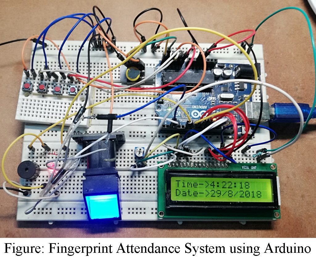
The project posted here is a simple Fingerprint Attendance System using Arduino and can be very useful for any place where attendance is taken for maintaining registers like offices, schools, etc. Previously, we had posted RFID based attendance system, Arduino Fingerprint Sensor Lock, etc.
The project posted here utilizes a thumb impression for taking attendance. The Fingerprint Attendance System using Arduino is based on a simple algorithm called matching algorithm and is compared with previously stored templates of fingerprints against the user’s fingerprint for authentication.
Maintaining a register for attendance is normally used for a traditional attendance system, but it is much more tedious. In this attendance system, the user places a finger on the sensor, the attendance is taken and the message is displayed on LCD along with the person’s name.
Circuit description of Fingerprint Attendance System using Arduino
The circuit shown in Figure 1 utilizes a 5V power supply which can be taken out from the Arduino board. The brain or processing component of the project Fingerprint Attendance System using Arduino is an Arduino board. As we all know, the Arduino board is based on an ATmega328/ATmega328P microcontroller. It is equipped with 14 digital Input or output pins multiplexed together, 6 analog inputs with inbuilt 32k flash memory. It also has a 16MHz crystal oscillator, a USB connection power jack, an ICSP header, and a reset button. Arduino uno board can be programmed using Arduino IDE software.

Fingerprint Sensor Module | Fingerprint Attendance System using Arduino
Fingerprint sensor module R305 (connected across CON1) has a UART interface with a direct connection with the Arduino UNO board. The user can store fingerprint samples in the module which can be configured in 1:1 or 1:N mode for identification for the right user.
The fingerprint sensor module R305 is powered with a +5V power supply which is connected to a 5V pin of Arduino board. Tx and Rx pin of the fingerprint sensor module is connected to Arduino digital pins 2 and 3 as shown in the circuit diagram. This connection is used for serial communication because only one individual pin is used for the transmitter and receiver thus parallel communication is not possible.
LCD Module | Fingerprint Attendance System using Arduino
A 16×2 alphanumeric LCD is used to display messages during operations like name, authentication, etc. The higher-order data pin of the LCD (pin 11, 12, 13, and 14) are connected to digital pins 8, 9, 10, and 11 of the Arduino uno board. The RS and E pin of LCD is connected to pins 12 and 13 of the Arduino uno board. RW pin of LCD is grounded because we only perform write operation in LCD. Preset VR1 is used to adjust the contrast of LCD. Pin no 15 and 16 of LCD not shown in the circuit diagram is used to glow backlight LED.
RTC Module | Fingerprint Attendance System using Arduino
The circuit Fingerprint Attendance System using Arduino also utilizes an RTC (Real Time Clock) module for storing the date and time of attendance. In this project, we used DS1307 RTC, which is a serial real-time clock IC with inbuilt various types of functions like calendar, 24-hour, and 12-hour time format with AM and PM indication. Two-line SDA and SCL of the DS1307 module are connected to analog pins A4 and A5 of the Arduino uno board as shown in Figure 1. The module has an inbuilt 3V button cell which helps the RTC module to run internally for a few days (approx. 10 days) even if the external power supply is not connected.
The four switches SW1 to SW4 are connected to four analog pins A0 to A3 of Arduino uno board respectively. Switch SW1 and SW2 are multiplexed i.e. various operation is performed by a single switch. The table shown below explains the operation of switches used in the circuit diagram.
| Table 1: Operation of Switch | ||
| S.N. | Switch | Operations |
| 1. | SW1 | ENROLL/BACK/DOWNLOAD |
| 2. | SW2 | DELETE/OK/RESET |
| 3. | SW3 | UP |
| 4. | SW4 | DOWN |
To Enroll new users.
- Power on the circuit.
- Press the Enroll switch (SW1), and follow the message displayed on the LCD.
- Users input the ID by using the Up and Down switch (SW3 and SW3).
- Press the OK switch (SW2)
- A message on the LCD screen is displayed and asks the user to put a finger on the fingerprint module. And follow the message as shown in LDC i.e. remove the finger and again put finger on the module.
- The system stores the fingerprint image in memory i.e. the user is registered and can take attendance.
To Delete Existing User
- Press the DELETE switch (SW2).
- LCD asks for the user ID to delete.
- User ID is selected by sculling UP and DOWN using switches SW3 and SW4.
- If ID is selected press the OK switch (SW2).
- A confirmation message is displayed on the LCD.
Glowing LED1 is used to indicate whether the system is ready or not whereas the piezo buzzer is used for the sound alert.
Software: Software of Fingerprint Attendance System Arduino is written in Arduino Programming language and is compiled using Arduino IDE. You can directly download the software code from the link given below.
|
1 2 3 4 5 6 7 8 9 10 11 12 13 14 15 16 17 18 19 20 21 22 23 24 25 26 27 28 29 30 31 32 33 34 35 36 37 38 39 40 41 42 43 44 45 46 47 48 49 50 51 52 53 54 55 56 57 58 59 60 61 62 63 64 65 66 67 68 69 70 71 72 73 74 75 76 77 78 79 80 81 82 83 84 85 86 87 88 89 90 91 92 93 94 95 96 97 98 99 100 101 102 103 104 105 106 107 108 109 110 111 112 113 114 115 116 117 118 119 120 121 122 123 124 125 126 127 128 129 130 131 132 133 134 135 136 137 138 139 140 141 142 143 144 145 146 147 148 149 150 151 152 153 154 155 156 157 158 159 160 161 162 163 164 165 166 167 168 169 170 171 172 173 174 175 176 177 178 179 180 181 182 183 184 185 186 187 188 189 190 191 192 193 194 195 196 197 198 199 200 201 202 203 204 205 206 207 208 209 210 211 212 213 214 215 216 217 218 219 220 221 222 223 224 225 226 227 228 229 230 231 232 233 234 235 236 237 238 239 240 241 242 243 244 245 246 247 248 249 250 251 252 253 254 255 256 257 258 259 260 261 262 263 264 265 266 267 268 269 270 271 272 273 274 275 276 277 278 279 280 281 282 283 284 285 286 287 288 289 290 291 292 293 294 295 296 297 298 299 300 301 302 303 304 305 306 307 308 309 310 311 312 313 314 315 316 317 318 319 320 321 322 323 324 325 326 327 328 329 330 331 332 333 334 335 336 337 338 339 340 341 342 343 344 345 346 347 348 349 350 351 352 353 354 355 356 357 358 359 360 361 362 363 364 365 366 367 368 369 370 371 372 373 374 375 376 377 378 379 380 381 382 383 384 385 386 387 388 389 390 391 392 393 394 395 396 397 398 399 400 401 402 403 404 405 406 407 408 409 410 411 412 413 414 415 416 417 418 419 420 421 422 423 424 425 426 427 428 429 430 431 432 433 434 435 436 437 438 439 440 441 442 443 444 445 446 447 448 449 450 451 452 453 454 455 456 457 458 459 460 461 462 463 464 465 466 467 468 469 470 471 472 473 474 475 476 477 478 479 480 481 482 483 484 485 486 487 488 489 490 491 492 493 494 495 496 497 498 499 500 501 502 503 504 505 506 507 508 509 510 511 512 513 514 515 516 517 518 519 520 521 522 523 524 525 526 527 528 529 530 531 532 533 534 535 536 537 538 539 540 541 542 543 544 545 546 547 548 549 550 551 552 553 554 555 556 557 558 559 560 561 562 563 564 565 566 567 568 569 570 571 572 573 574 575 576 577 578 579 580 581 582 583 584 585 586 587 588 589 590 591 592 593 594 595 596 597 598 599 600 601 602 603 604 605 606 607 608 609 610 611 |
#include<EEPROM.h> #include<LiquidCrystal.h> LiquidCrystal lcd(13,12,11,10,9,8); #include <SoftwareSerial.h> SoftwareSerial fingerPrint(2, 3); #include <Wire.h> #include "RTClib.h" RTC_DS1307 rtc; #include "Adafruit_Fingerprint.h" uint8_t id; Adafruit_Fingerprint finger = Adafruit_Fingerprint(&fingerPrint); #define enroll 14 #define del 15 #define up 16 #define down 17 #define match 5 #define indFinger 7 #define buzzer 5 #define records 4 // replace number (4) with number of user in system //put 5 for 5 user int user1,user2,user3,user4,user5; DateTime now; void setup() { delay(1000); lcd.begin(16,2); Serial.begin(9600); pinMode(enroll, INPUT_PULLUP); pinMode(up, INPUT_PULLUP); pinMode(down, INPUT_PULLUP); pinMode(del, INPUT_PULLUP); pinMode(match, INPUT_PULLUP); pinMode(buzzer, OUTPUT); pinMode(indFinger, OUTPUT); digitalWrite(buzzer, LOW); if(digitalRead(enroll) == 0) { digitalWrite(buzzer, HIGH); delay(500); digitalWrite(buzzer, LOW); lcd.clear(); lcd.print("Waiting..."); lcd.setCursor(0,1); lcd.print("Data Downloading"); Serial.println("Waiting..."); Serial.println("Data Downloading"); Serial.println(); Serial.print("S.N. "); for(int i=0;i<records;i++) { digitalWrite(buzzer, HIGH); delay(500); digitalWrite(buzzer, LOW); Serial.print(" User ID"); Serial.print(i+1); Serial.print(" "); } Serial.println(); int eepIndex=0; for(int i=0;i<30;i++) { if(i+1<10) Serial.print('0'); Serial.print(i+1); Serial.print(" "); eepIndex=(i*7); download(eepIndex); eepIndex=(i*7)+210; download(eepIndex); eepIndex=(i*7)+420; download(eepIndex); eepIndex=(i*7)+630; download(eepIndex); //if 5th uer is added // eepIndex=(i*7)+840; // download(eepIndex); Serial.println(); } } if(digitalRead(del) == 0) { lcd.clear(); lcd.print("Waiting..."); lcd.setCursor(0,1); lcd.print("Reseting....."); for(int i=1000;i<1005;i++) EEPROM.write(i,0); for(int i=0;i<841;i++) EEPROM.write(i, 0xff); lcd.clear(); lcd.print("System Reset"); delay(1000); } lcd.clear(); lcd.print(" Attendance "); lcd.setCursor(0,1); lcd.print(" System "); delay(2000); lcd.clear(); lcd.print("Best Eng Project"); lcd.setCursor(0,1); lcd.print("Krishna Keshav"); delay(2000); digitalWrite(buzzer, HIGH); delay(500); digitalWrite(buzzer, LOW); for(int i=1000;i<1000+records;i++) { if(EEPROM.read(i) == 0xff) EEPROM.write(i,0); } finger.begin(57600); Serial.begin(9600); lcd.clear(); lcd.print("Finding Module"); lcd.setCursor(0,1); delay(1000); if (finger.verifyPassword()) { Serial.println("Found fingerprint sensor!"); lcd.clear(); lcd.print("Module Found"); delay(1000); } else { Serial.println("Did not find fingerprint sensor :("); lcd.clear(); lcd.print("module not Found"); lcd.setCursor(0,1); lcd.print("Check Connections"); while (1); } if (! rtc.begin()) Serial.println("Couldn't find RTC"); // rtc.adjust(DateTime(F(__DATE__), F(__TIME__))); if (! rtc.isrunning()) { Serial.println("RTC is NOT running!"); // following line sets the RTC to the date & time this sketch was compiled rtc.adjust(DateTime(F(__DATE__), F(__TIME__))); // This line sets the RTC with an explicit date & time, for example to set // January 21, 2014 at 3am you would call: // rtc.adjust(DateTime(2014, 1, 21, 3, 0, 0)); } lcd.setCursor(0,0); lcd.print("Press Match to "); lcd.setCursor(0,1); lcd.print("Start System"); delay(2000); user1=EEPROM.read(1000); user2=EEPROM.read(1001); user3=EEPROM.read(1002); user4=EEPROM.read(1003); user5=EEPROM.read(1004); lcd.clear(); digitalWrite(indFinger, HIGH); } void loop() { now = rtc.now(); lcd.setCursor(0,0); lcd.print("Time->"); lcd.print(now.hour(), DEC); lcd.print(':'); lcd.print(now.minute(), DEC); lcd.print(':'); lcd.print(now.second(), DEC); lcd.print(" "); lcd.setCursor(0,1); lcd.print("Date->"); lcd.print(now.day(), DEC); lcd.print('/'); lcd.print(now.month(), DEC); lcd.print('/'); lcd.print(now.year(), DEC); lcd.print(" "); delay(500); int result=getFingerprintIDez(); if(result>0) { digitalWrite(indFinger, LOW); digitalWrite(buzzer, HIGH); delay(100); digitalWrite(buzzer, LOW); lcd.clear(); lcd.print("ID:"); lcd.print(result); lcd.setCursor(0,1); lcd.print("Waiting..."); delay(1000); attendance(result); lcd.clear(); lcd.print("Attendance "); lcd.setCursor(0,1); lcd.print("Registed"); delay(1000); digitalWrite(indFinger, HIGH); return; } checkKeys(); delay(300); } // dmyyhms - 7 bytes void attendance(int id) { int user=0,eepLoc=0; if(id == 1) { eepLoc=0; user=user1++; } else if(id == 2) { eepLoc=210; user=user2++; } else if(id == 3) { eepLoc=420; user=user3++; } else if(id == 4) { eepLoc=630; user=user4++; } /*else if(id == 5) // if 5th user is used { eepLoc=840; user=user5++; }*/ else return; int eepIndex=(user*7)+eepLoc; EEPROM.write(eepIndex++, now.hour()); EEPROM.write(eepIndex++, now.minute()); EEPROM.write(eepIndex++, now.second()); EEPROM.write(eepIndex++, now.day()); EEPROM.write(eepIndex++, now.month()); EEPROM.write(eepIndex++, now.year()>>8 ); EEPROM.write(eepIndex++, now.year()); EEPROM.write(1000,user1); EEPROM.write(1001,user2); EEPROM.write(1002,user3); EEPROM.write(1003,user4); // EEPROM.write(4,user5); // figth user } void checkKeys() { if(digitalRead(enroll) == 0) { lcd.clear(); lcd.print("Waiting..."); delay(1000); while(digitalRead(enroll) == 0); Enroll(); } else if(digitalRead(del) == 0) { lcd.clear(); lcd.print("Waiting..."); delay(1000); delet(); } } void Enroll() { int count=1; lcd.clear(); lcd.print("Enter Finger ID:"); while(1) { lcd.setCursor(0,1); lcd.print(count); if(digitalRead(up) == 0) { count++; if(count>records) count=1; delay(500); } else if(digitalRead(down) == 0) { count--; if(count<1) count=records; delay(500); } else if(digitalRead(del) == 0) { id=count; getFingerprintEnroll(); for(int i=0;i<records;i++) { if(EEPROM.read(i) != 0xff) { EEPROM.write(i, id); break; } } return; } else if(digitalRead(enroll) == 0) { return; } } } //Function To delete Existing User void delet() { int count=1; lcd.clear(); lcd.print("Enter Finger ID"); while(1) { lcd.setCursor(0,1); lcd.print(count); if(digitalRead(up) == 0) { count++; if(count>records) count=1; delay(500); } else if(digitalRead(down) == 0) { count--; if(count<1) count=records; delay(500); } else if(digitalRead(del) == 0) { id=count; deleteFingerprint(id); for(int i=0;i<records;i++) { if(EEPROM.read(i) == id) { EEPROM.write(i, 0xff); break; } } return; } else if(digitalRead(enroll) == 0) { return; } } } //Funbction to convert finger print image to templete uint8_t getFingerprintEnroll() { int p = -1; lcd.clear(); lcd.print("finger ID:"); lcd.print(id); lcd.setCursor(0,1); lcd.print("Place Finger"); delay(2000); while (p != FINGERPRINT_OK) { p = finger.getImage(); switch (p) { case FINGERPRINT_OK: Serial.println("Image taken"); lcd.clear(); lcd.print("Image taken"); break; case FINGERPRINT_NOFINGER: Serial.println("No Finger"); lcd.clear(); lcd.print("No Finger"); break; case FINGERPRINT_PACKETRECIEVEERR: Serial.println("Communication error"); lcd.clear(); lcd.print("Comm Error"); break; case FINGERPRINT_IMAGEFAIL: Serial.println("Imaging error"); lcd.clear(); lcd.print("Imaging Error"); break; default: Serial.println("Unknown error"); lcd.clear(); lcd.print("Unknown Error"); break; } } // OK success! p = finger.image2Tz(1); switch (p) { case FINGERPRINT_OK: Serial.println("Image converted"); lcd.clear(); lcd.print("Image converted"); break; case FINGERPRINT_IMAGEMESS: Serial.println("Image too messy"); lcd.clear(); lcd.print("Image too messy"); return p; case FINGERPRINT_PACKETRECIEVEERR: Serial.println("Communication error"); lcd.clear(); lcd.print("Comm Error"); return p; case FINGERPRINT_FEATUREFAIL: Serial.println("Could not find fingerprint features"); lcd.clear(); lcd.print("Feature Not Found"); return p; case FINGERPRINT_INVALIDIMAGE: Serial.println("Could not find fingerprint features"); lcd.clear(); lcd.print("Feature Not Found"); return p; default: Serial.println("Unknown error"); lcd.clear(); lcd.print("Unknown Error"); return p; } Serial.println("Remove finger"); lcd.clear(); lcd.print("Remove Finger"); delay(2000); p = 0; while (p != FINGERPRINT_NOFINGER) { p = finger.getImage(); } Serial.print("ID "); Serial.println(id); p = -1; Serial.println("Place same finger again"); lcd.clear(); lcd.print("Place Finger"); lcd.setCursor(0,1); lcd.print(" Again"); while (p != FINGERPRINT_OK) { p = finger.getImage(); switch (p) { case FINGERPRINT_OK: Serial.println("Image taken"); break; case FINGERPRINT_NOFINGER: Serial.print("."); break; case FINGERPRINT_PACKETRECIEVEERR: Serial.println("Communication error"); break; case FINGERPRINT_IMAGEFAIL: Serial.println("Imaging error"); break; default: Serial.println("Unknown error"); return; } } // OK success! p = finger.image2Tz(2); switch (p) { case FINGERPRINT_OK: Serial.println("Image converted"); break; case FINGERPRINT_IMAGEMESS: Serial.println("Image too messy"); return p; case FINGERPRINT_PACKETRECIEVEERR: Serial.println("Communication error"); return p; case FINGERPRINT_FEATUREFAIL: Serial.println("Could not find fingerprint features"); return p; case FINGERPRINT_INVALIDIMAGE: Serial.println("Could not find fingerprint features"); return p; default: Serial.println("Unknown error"); return p; } // OK converted! Serial.print("Creating model for #"); Serial.println(id); p = finger.createModel(); if (p == FINGERPRINT_OK) { Serial.println("Prints matched!"); } else if (p == FINGERPRINT_PACKETRECIEVEERR) { Serial.println("Communication error"); return p; } else if (p == FINGERPRINT_ENROLLMISMATCH) { Serial.println("Fingerprints did not match"); return p; } else { Serial.println("Unknown error"); return p; } Serial.print("ID "); Serial.println(id); p = finger.storeModel(id); if (p == FINGERPRINT_OK) { Serial.println("Stored!"); lcd.clear(); lcd.print("Stored!"); delay(2000); } else if (p == FINGERPRINT_PACKETRECIEVEERR) { Serial.println("Communication error"); return p; } else if (p == FINGERPRINT_BADLOCATION) { Serial.println("Could not store in that location"); return p; } else if (p == FINGERPRINT_FLASHERR) { Serial.println("Error writing to flash"); return p; } else { Serial.println("Unknown error"); return p; } } //Function to compare finger print image with stored IDs for matching int getFingerprintIDez() { uint8_t p = finger.getImage(); if (p != FINGERPRINT_OK) return -1; p = finger.image2Tz(); if (p != FINGERPRINT_OK) return -1; p = finger.fingerFastSearch(); if (p != FINGERPRINT_OK) { lcd.clear(); lcd.print("Finger Not Found"); lcd.setCursor(0,1); lcd.print("Try Later"); delay(2000); return -1; } // found a match! Serial.print("Found ID #"); Serial.print(finger.fingerID); return finger.fingerID; } uint8_t deleteFingerprint(uint8_t id) { uint8_t p = -1; lcd.clear(); lcd.print("Please wait"); p = finger.deleteModel(id); if (p == FINGERPRINT_OK) { Serial.println("Deleted!"); lcd.clear(); lcd.print("Figer Deleted"); lcd.setCursor(0,1); lcd.print("Successfully"); delay(1000); } else { Serial.print("Something Wrong"); lcd.clear(); lcd.print("Something Wrong"); lcd.setCursor(0,1); lcd.print("Try Again Later"); delay(2000); return p; } } //Function for Download the Data fro EEPROM to Serial Monitor void download(int eepIndex) { if(EEPROM.read(eepIndex) != 0xff) { Serial.print("T->"); if(EEPROM.read(eepIndex)<10) Serial.print('0'); Serial.print(EEPROM.read(eepIndex++)); Serial.print(':'); if(EEPROM.read(eepIndex)<10) Serial.print('0'); Serial.print(EEPROM.read(eepIndex++)); Serial.print(':'); if(EEPROM.read(eepIndex)<10) Serial.print('0'); Serial.print(EEPROM.read(eepIndex++)); Serial.print(" D->"); if(EEPROM.read(eepIndex)<10) Serial.print('0'); Serial.print(EEPROM.read(eepIndex++)); Serial.print('/'); if(EEPROM.read(eepIndex)<10) Serial.print('0'); Serial.print(EEPROM.read(eepIndex++)); Serial.print('/'); Serial.print(EEPROM.read(eepIndex++)<<8 | EEPROM.read(eepIndex++)); } else { Serial.print("---------------------------"); } Serial.print(" "); } |
CLICK HERE TO DOWNLOAD THE SOFTWARE CODE
Click Here to Download the Library File
PARTS LIST OF FINGERPRINT ATTENDANCE SYSTEM USING ARDUINO
R1 = 1 KΩ, Resistor
VR1 = 10 KΩ, Preset
ARD1 = Arduino UNO Board
RTC Module = DS1307
Fingerprint Sensor Module = R305
LCD1 = 16×2 LCD
SW1 – SW4 = Push-to-on Switch
LED1 = 5mm any color LED
BUZ1 = Piezo Buzzer
how to download data from arduino??
you cannot download the data from Arduino, in that case you have to add SD card for data log and download.
Instead of Arduino what can we use ?