Sometimes we have to check the water supply pipeline from the municipal whether water is coming or not. Though the supply interval is fixed, the supply time may vary accordingly. It is quite possible to forget to switch on the motor, which results in no water in the reservoir. The article named, “Water Flow Detection with Alert System using 555 IC” is written to tackle such situations.
In this article, you will learn to construct a simple water flow detector circuit. The circuit basically triggers the alarm when the water flows in the pipe.
Circuit Description of Water Flow Detection with Alert System using 555 IC
The circuit of the Water Flow Detection and Alert system is divided into two major sections
- Water flow detection unit
- Alert Unit
Water flow detection unit
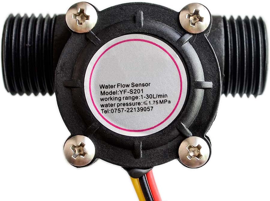
Figure 1: Flow Sensor
For water flow detection, we require a sensor. A very cheap and easily available alternative is YF-S201 water flow. This sensor has a hall effect mechanism that produces a PWM pulse of 5V (TTL- supported) as an output when water flows through the rotor and the rotor rotates. The rate of PWM pulse output changes (i.e. frequency of pulse) along with the increase or decrease of water flow rate. The conversion of flow rate to PWM frequency is:

Note: Operating Flow Rate Range: 1 to 30 Litres/Min
This sensor has three pins, Vcc pin (usually RED), GND pin (usually BLACK), and Signal pin (usually YELLOW). These three wires of the sensor are connected to the 3-pin single inline connector (SIL3). The resistor R13 is introduced for current limiting purposes and diode D8 to block reverse voltages. Now, keeping in mind the fluctuating output of the sensor, it can be used as a trigger with the application of a high-pass filter. A simple 1st order high pass filter will only allow a fluctuating signal with a frequency above its cut-off frequency to pass through. The cut-off frequency point can be calculated using the equation following equation:
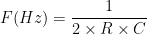
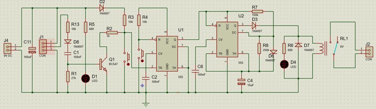 Figure 2: Water Flow Detection with Alert System using 555 IC
As shown in Figure 2, we use resistor R1 of 27KΩ and capacitor C1 of 10nF to design a high-pass filter. The cut-off frequency is calculated as:

This filter only allows signals of frequency greater than 590 Hz. So calculating the minimum flow rate required from the above-mentioned relation between frequency and flow rate.

or, 


Converting into minutes,

We are using a 555 timer in bistable mode and an NPN transistor as an input trigger for the timer, as shown in Figure 2. Let’s first familiarize yourself with the pin connections of this timer IC in Bistable Multivibrator mode. The 9V positive power supply is supplied to VCC (Pin 8) and Reset pin (Pin 4) and Trigger pin (Pin 2). The diode D2 is introduced to protect the IC from reverse voltage. The resistors R3 and R4 limit the current flowing into the IC pins. Pin 2 and Pin 4 are individually connected to GND through switches for low triggers. The Control voltage pin (pin 5) is connected to the ground through a ceramic capacitor. Threshold pin (pin 6), Discharge pin (pin 7), and Ground pin (pin 1) are sorted to GND. The Output pin (pin 3) is used to drive another 555-timer IC.
Working of Bistable mode 555 Timer IC
After detecting a fluctuating signal via the high pass filter, transistor Q1 is turned ON. This transistor initiates a negative pulse to the Trigger pin (pin 2) of the 555 Timer (U1). As a result, output from Pin 3 becomes high. The same result is obtained when the switch (SW1) connected with Pin 2 is pressed, shorting the Trigger pin with the ground. The Output Pin (pin 3) continuously produces high until you short the Reset Pin (pin 4) to GND by pressing a switch (SW2). In this way, we achieve our objective of the system activator phase.
Alert Unit
For this unit, we are again using a 555 timer (U2), but now configured in Astable Multivibrator mode. The pin and component connections are shown below:
The driving signal from the previous timer IC is connected to Pin 4 and Pin 8. Pin 5 is connected to the ground through a ceramic capacitor. Pin 2 and Pin 6 are connected to GND through an electrolytic capacitor C4. Diodes D3, D6, and D7 pave a forward pathway for signal flow as well as protect against reverse voltage. Pin 3 is used to drive a 6V Relay switch with LED. The capacitor C4, and resistors R7 and R8 associated with pins 2,6, and 7 influence the duration of operation (i.e. ON and OFF duration).
When the output of Timer IC U1 produces high output, the IC U2 starts to generate alternating high and low outputs for a predefined time. The high output from U2 energizes the relay (RL1) for the ON duration. We can calculate the ON time and OFF time intervals mathematically as follows:
Mathematical calculation for time intervals:
For High/ON Time interval:


For Low/OFF Time interval:


Total cycle time:

Duty cycle:
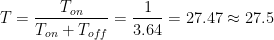
So the relay switch (RL1) is energized for roughly around 1.04 second and stays off for roughly 2.6 seconds. The 2-pin connector J2 can connect an alarm or any other type of indicator.
Power Supply Arrangement for Water Flow Detector:
Normally a 9V battery supply can be used to power the system by connecting connector J4, but in case you want to directly supply an AC main, the below circuit can be used to power the system.
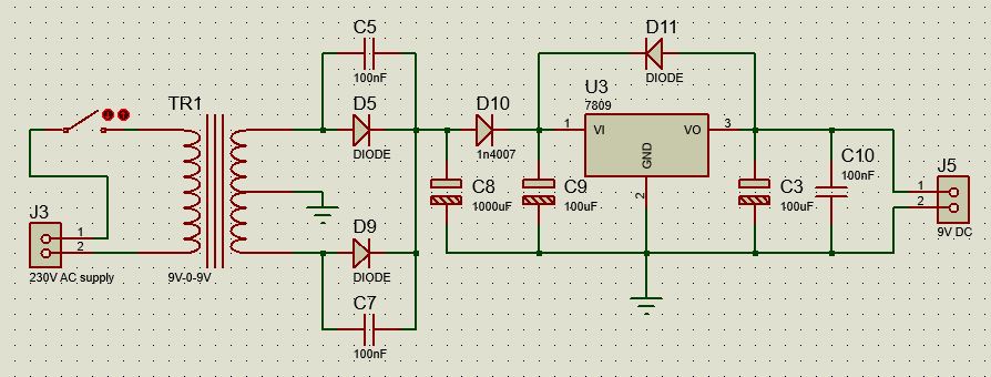
Figure 3: Power Supply Circuit
Components list of Water Flow Detection with Alert System using 555 IC
| Resistors: (all ¼-watt, ± 5% Carbon Unless Stated Otherwise) |
| R2 = 1kΩ R1 = 27kΩ R3,R4,R13 = 10kΩ R5,R6 = 680 Ω R7 = 100kΩ R8 = 250kΩ |
| Capacitors |
| C1,C2,C5,C6,C7,C10 = 100nF (Ceramic Disc) C3,C9,C11 = 100uF (Electrolytic Capacitor) C4 = 15uF (Electrolytic Capacitor) C8 = 1000uF (Electrolytic Capacitor) |
| Semiconductors |
| D1,D4 = 5mm LED D2,D3,D5,D6,D7,D8,D9,D10,D11= 1N4007 U1,U2 = NE555 U3 = 7809 (Fixed Voltage Regulator) |
| Miscellaneous: |
| SW1, SW2 = Push to on Switch RL1 = 6V SPDT 100Ω Relay 9V Power Supply TR1 = 9V-0-9V Transformer J2,J3,J4,J5 = 2-Pin connectors J1 = 3-Pin connectors |
Please describe working function of circuit
Quise decir que alimente R4 de la línea de Vcc que alimenta a R3…
Yes, you should connect the Vcc pin (pin 8) of the 555 timer to the Vcc line.