In this article, we will learn to interface a UV sensor with Arduino nano. The term “UV” stands for ultraviolet and UV sensors are used to measure the power or intensity of incident ultraviolet (UV) radiation at a particular area. This form of electromagnetic radiation (UV radiation) has shorter wavelengths than visible radiation but is still longer than x-rays.
Some theory on UV spectrum: The UV spectrum ranges from 100 nm to 400 nm and is divided into three bands.
- UVA (315-400 nm) – least harmful but stay away from extended exposures
- UVB (280-315 nm) – little harmful (does not penetrate the skin)
- UVC (100-280 nm) – most harmful (does not reach earth)
The UVA band accounts for 95% of the UV radiation reaching the Earth’s surface. It can penetrate into the deeper layers of the skin and is responsible for the immediate tanning effect. UVB is very biologically active but cannot penetrate beyond the superficial skin layers and is responsible for delayed tanning and burning. UVC is the most damaging type of UV radiation. However, it is completely filtered by the atmosphere and does not reach the earth’s surface. Some applications of UV sensors include the printing industry, medical and pharmaceutical sectors, the automobile sector, robotics, and many more. These sensors play a vital role in determining exposure to ultraviolet radiation in the laboratory or environmental settings for production.
In this article, we will be working with a “UV-sensor v1.1” from Grove. The Grove – UV Sensor is based on the sensor GUVA-S12D from GenUV (Genuine UV Technology). The sensor GUVA-S12D (UV detector) is considered to be a true UV detector that detects light ranging from 240nm to 370nm most effectively [i.e. some UV-B and most of the UV-A spectrum]. This “GUVA-S12D” generates an analog voltage output proportional to the UV Index of UV light falling on the detector.
Features of UV Sensor:
- Fast and responsive
- Schottky-type photodiode sensor
- Good sensitivity
- Low power consumption
- Highly stable output
- Low dark current
Specification of UV Sensor:
- Operating Temperature: -30℃ to +85℃
- Operating Voltage: 3.3V to 5.1V (typically 5V)
- Response Wavelength: 240nm to 370nm
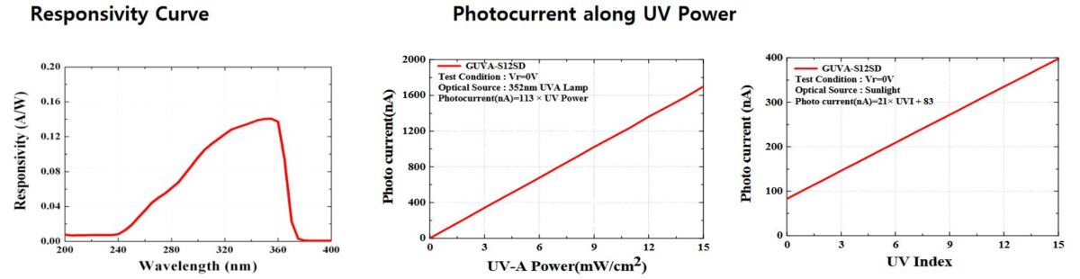
- Photocurrent: 21nA @ 1 UV-index
- Responsivity: 0.14 A/W @ 350nm
- Photo-current: 113 nA (using UVA lamp) or 21nA (sunlight)
Working of UV sensor Module:
A UV sensor module consists of a “GUVA-S12D” sensor with a UV-sensitive photodiode (Schottky-type). This sensor generates small amounts of photocurrent (nA) in proportion to UV exposure. Then an op-amp in the Grove-UV sensor module (OPA2333A) amplifies the nano-ampere (nA) level signal to a more manageable and meaningful voltage output. The output is in an analog form which can be fed into ADC to produce an equivalent digital voltage. Then is signal can be used by external micro-controllers to perform specific actions (such as alerts).
As per the grove documentation, we can find out the UV index from the modules output voltage using two equations as shown:
illumination intensity = 307 * Vsig
UV Index = illumination intensity/200
Here, “Vsig” is the value of voltage measured from the SIG pin of the Grove interface (unit: V) whereas “illumination intensity” (unit: mW/cm^2) is the combined strength of UV lights within the range: 240nm~370nm.
[Note: The sensor measurements are converted to the UV index, but the values are a rough estimation of the EPA standard UV index.]
Interfacing UV sensor with Arduino:
As the figure demonstrates, the I2C_LCD has its VCC & GND pin connected to 5V & ground, whereas its SDA & SCL pin to analog pins A4 & A5 of Nano.
For the UV sensor wiring below table is given:
| UV Sensor pins | Arduino Nano |
| VCC | 5V |
| GND | GND |
| SIG (output signal) | A0 (analog pin) |
| NC (not connected) | – |
The groove UV sensor consists of 4 pins namely VCC, GND, NC, and SIG pin. This module is operable in both 3.3 and 5V (typically using 5V). The 5V supply is connected to the VCC pin, the GND pin is connected to the power ground, and the SIG pin is connected to any analog pin of the nano whereas, the NC pin is left out (introduced just for easy setup connections).
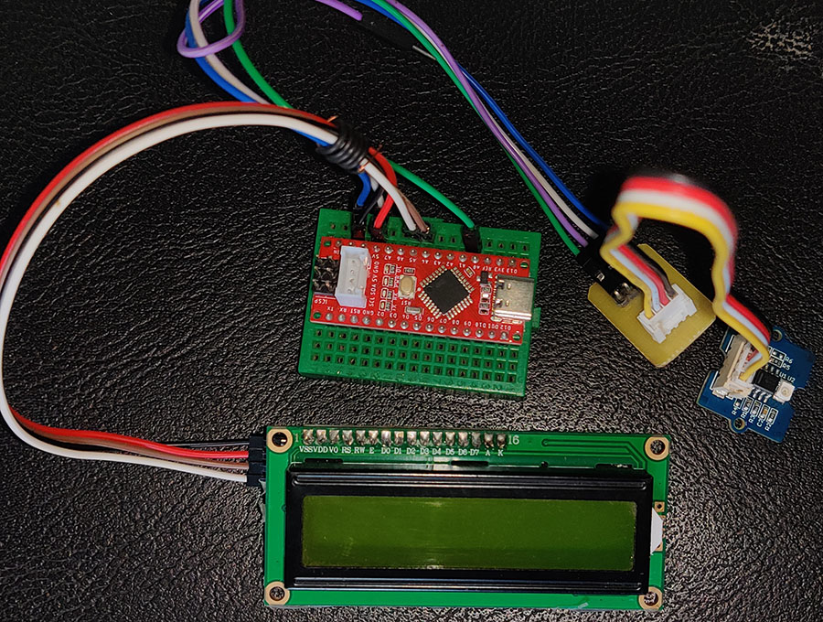
Figure: Interfacing UV Sensor with Arduino Nano
Arduino Software Code:
After successfully interfacing the sensor with the nano, you can extract the sensor reading and display them in the following code:
|
1 2 3 4 5 6 7 8 9 10 11 12 13 14 15 16 17 18 19 20 21 22 23 24 25 26 27 28 29 30 31 32 33 34 35 36 37 38 39 40 41 42 |
#include <LiquidCrystal_I2C.h> LiquidCrystal_I2C lcd(0x27,16,2); #define UV_pin A0 // UV sensor reading pin void setup() { Serial.begin(9600); lcd.init(); lcd.backlight(); } void loop() { int sensorValue; long sum=0; for(int i=0;i<1024;i++) // accumulate readings for 1024 times { sensorValue=analogRead(UV_pin); // 0 to 255 sum+=sensorValue; delay(2); } float Vsig = sum/1024; // get mean value for analog voltage Serial.print("Avg Vsig: "); Serial.println(Vsig); // calculate the rough index estimation of EPA standard float illuInten = 307*Vsig; float index = illuInten/200; Serial.print("The current UV index is:"); Serial.println(index); Serial.println(); //LCD Display lcd.clear(); lcd.print("UV index : "); lcd.print(index); lcd.setCursor(0,1); lcd.print(Vsig); delay(1000); } |