Here is a simple project CCTV Switcher circuit using timer IC 555 and decade counter IC 4017. The basic function of this project is to switch between different CCTV cameras sequentially i.e. one CCTV output is displayed on TV at a time.
A CCTV (Closed Circuit Telephone) camera is used for video surveillance by using a video camera. Sometimes one CCTV camera is not sufficient for surveillance entire area thus we have to use multiple cameras to cover the entire area of surveillance. The circuit posted here control four CCTV camera and display the output of one CCTV camera to a TV monitor at a time.
Circuit description of CCTV Switcher using 555 IC
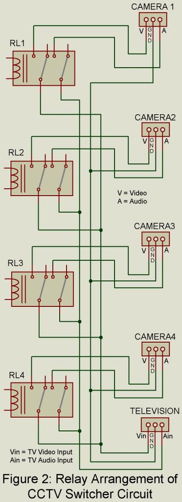
The CCTV Switcher circuit using 555 IC and 4017-decade counter is shown in figure 1. Similarly, the relay connection circuit is shown in figure 2. The entire circuit of CCTV Switcher circuit is built around 555 timer IC, a 4017-decade counter IC, four DPDT relay with its switching circuit, and a few other electronic components like resistor, capacitor, diode, etc. for working flawlessly.

12V DC power supply is given to the circuit through connector CON1, where diode D2 block reverses current from the circuit to power supply. Capacitors C1 and C2 filter the ripple contains in input DC supply
Timer IC 555 (IC1) is configured in astable multivibrator mode whose period is determined by resistor R1 and R2, variable resistor VR1, and capacitor C3. The charging of the capacitor is done by resistor R1 and diode D1 where discharging is done by resistor R1 and variable resistor VR1 through discharge pin (pin 7) of IC1. The output of IC1 (555) from pin 3 is given to the clock pin (pin 14) of IC2 for counting the clock pulse.
The second clock pin of IC2 is grounded through switch SW1. We had only used four (Q0 to Q4) out of 10 outputs of IC1 which are ON and OFF sequentially after every clock pulse. Generally, output Q0 goes high when the circuit is reset and 1st clock pulse is given to pin 14 then output Q2 goes high after the second clock pulse, and so on up-to output Q9 becomes high. After the 10th clock pulse, the circuit is reset. But here in this circuit, we had force reset after the 4th clock pulse by connecting output pin Q4 to reset pin (pin 15). Then when 1st clock pulse is given to the IC2 output Q0 becomes high for a fixed interval of time. Similarly, when the 2nd clock pulse is given to the circuit output Q1 is high and so on up to Q3 is high.
Switching Circuit | CCTV Switcher Circuit using Timer IC 555
The switching circuit is designed around the transistor. Four individual relays utilize four individual transistors. When the output is high its corresponding transistor goes in saturation state as a result relay energized and the CCTV camera becomes ON. DPDT is used here because it will switch audio and video signals coming from the camera. The four LEDs are used to indicate energize of the relay i.e. glowing LED1 indicates relay RL1 is energized, LED2 indicates relay RL2 energize, and so on. The four resistors (R9 to R12) connected in series to LED is a current limiting resistor that protects LED from burning out. Diodes D3 to D6 is a fly-back diode that protects the coil of the relay.
NOTE: The period of switching between different CCTV cameras can be adjusted by variable resistor VR1. IF you require a large period you can replace VR1 with a 1M variable resistor.
Other Interesting projects posted in bestengineeringprojects.com
- Temperature controlled soldering iron station
- Staircase Switch Circuit
- Electronics Washing Machine Control | Circuit Diagram
- Automatic Suction Tank Motor Controller
PARTS LIST OF CCTV SWITCHER CIRCUIT USING 555 IC AND 4017 IC
| Resistors (all ¼-watt, ± 5% Carbon) |
| R1 = 10 KΩ
R2, R4 = 100 KΩ R3, R5 – R8 = 3.3 KΩ R9 – R12 = 680 Ω VR1 = 470 KΩ |
| Capacitors |
| C1 = 0.1 µF (Ceramic Disc)
C2 = 470 µF, 25V (Electrolytic Capacitor) C3 = 10 µF, 25V (Electrolytic Capacitor) C4 = 0.01 µF (Ceramic Disc) |
| Semiconductors |
| IC1 = NE555 (Timer IC)
IC2 = 4017B (Decade Counter) T1 – T4 = BC547 (General purpose NPN transistor) D1 = 1N4148 (Silicon Switching Signal Diode) D2 – D6 = 1N4007 (Silicon Rectifier Diode) LED1 – LED4 = 5mm any color LED |
| Miscellaneous |
| SW1 = push-to-off Switch
RL1 – RL4 = 12V, 2C/O relay CON1 = 2-pin connector 12V DC supply |