In this section we are going to analyze and troubleshoot the AM converter circuit. the converter, also known as autodyne circuit, is a combination of the local oscillator and the mixer in a single stage. We are also going to discuss the power supply and audio amplifier problems in this section
Upon completing this section, you should be able to
- Troubleshoot an AM converter circuit
- Identify an open input circuit
- Identify a dead or intermittent local oscillator circuit
- Identify causes for a dead and intermittent local oscillator
- Troubleshoot the receiver’s power supply
- Troubleshooting the receiver’s audio amplifier
The Converter Circuit
Figure 1 shows the converter stage (autodyne circuit) of an AM radio. The received RF input signal is fed into the base of Q1 from coils L1 and L2. The input AM radio signal is selected by tuning C1; notice also that C1 and C4 are ganged. When C1 is adjusted, C4 will be adjusted by the same amount. The local oscillator proportion of the converter stage is made up of L3, L4 and C4. As C4 is adjusted the oscillator frequency changes to maintain a difference frequency of 455 kHz above the received AM signa. The feedback capacitor C3 sends a portion of the oscillator signal from a tap on L4 back to the emitter of Q1. The received RF signal and the oscillator signal are mixed in Q1 to produce the IF, which is sent to L5. All frequencies except the 455-kHz IF signal is filtered out by the tuned circuit’s L5 and C5. Resistors R1 and R2 form a voltage divider network to bias the transistor’s base-emitter circuit. Resistor R3 acts as a dc stabilizer for the emitter circuit. Capacitor C2 is a decoupling capacitor to keep the IF frequency from being fed back to the base of Q1. Any IF signal present at the base would be shorted to ground. The transistor’s collector dc voltage is supplied by R4.
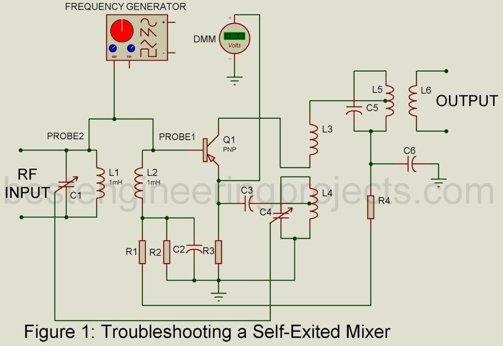
No AM RF Signal
If the received AM RF signal does not reach the base of Q1, no audio will be heard from the speaker. Noise may be heard when the tuning dial is moved across the band, but no station will come in. An exception might be where a strong AM radio station in close proximity bleeds through into the converter transistor. A good indication of a working converter stage is to monitor the emitter voltage using a DMM as depicted in figure 1. As the radio is tuned across the AM band, the voltage reading on DMM will change. An open winding in coil L1 will cause the receiver AM signal to be lost. If a test signal were injected at the base of Q1 (refer to figure 1 signal generator probe 1), it would be heard from the speaker. If the test signal were applied to L1 (figure 2 probe 2), no signal would be heard. If the coil L2 were open, AM reception would be lost. In addition, an open L2 will isolate the base from the resistor voltage divider network. As a result, the base-emitter bias would be removed and the transistor would cut off. Coils L1 and L2 in most AM receivers are part of the antenna system. The antenna consists of a ferrite metal stick with very fine wires making up the two coils. These fine wires very often break at the antenna r come loose from the printed circuit board, causing L1 or L2 to become open. Also, the wires from radio transformers usually break at the base of the transformer, where they are connected to the PCB. A dead converter stage can also result from a defective transistor.
Dead Local Oscillator Portion of Converter
Measuring the voltage at the emitter with a DMM and tuning the radio across the AM band is a good indication of oscillator operation. If this voltage changes as the radio is tuned, the oscillator can be assumed to be functioning. An oscilloscope at the emitter of transistor Q1 will show the oscillator waveform if it is present. If the local oscillator is dead (not operating), the signal will be missing and no voltage change will be detected by the DMM at the emitter of Q1. An open L4 will shut down the oscillator operation, the same is true for an open C4.
Poor AM Reception
A leaky capacitor C3 can cause erratic operation of the local oscillator circuit. Received radio stations will fade in and fade out as a result of this erratic operation of the oscillator. A station may fade out altogether and the converter quit working from a severely leaking capacitor. This is due to the loading effect on the emitter circuit of Q1. A local oscillator with poor tracking will affect radio reception at the high end or the low end of the AM band. A fault C4 and C1 are likely suspects if poor tracking occurs.
Symptoms are Likely Causes
The following table lists symptoms and the likely circuit components that can cause them.
Table 1: Converter Troubleshooting Chart |
|||
| S.N. | Symptom | Troubleshooting Check | Likely Trouble |
| 1. | No reception | Power OK; converter working | No input signal at base of Q1; L1 or L2 open; transistor bad |
| 2. | The station fade in and out | Q1’s emitter voltage fluctuates | Converter operation erratic; C3 leaky or open |
| 3. | No station heard from mid to low AM band | DMM voltage changes when the radio is tuned | LO not tracking across AM band; C1 or C4 faulty |
| 4. | No station heard from mid to high AM band | DMM voltage changes when the radio is tuned | LO not tracking across AM band; C1 or C4 faulty |
Suspected faulty capacitors should be tested. The best method for testing capacitors is to use a capacitor checker. Some DMMs on the market today have a capacitor check function. The capacitor values are small in the converter circuit and should be tested out of the circuit. Open coils can be found using the ohmmeter setting of the DMM. A good coil will measure low resistance and an open coil will measure a very high resistance. Coil can usually be measured without removing them from the circuit. if the converter transistor is suspect, test it with a transistor tester. Modern DMMs are equipped with this function. An open or shorted transistor can be tested with the DMM diode check setting or the ohmmeter setting.
Thanks for giving useful tips. My vintage AM radio with cassette tape recorder recently behaving very weird. It has two shortwave bands and a medium wave band. Sometime it receives and suddenly goes silent. At that time nothing can be heard in all 3 bands. Unexpectedly the radio starts to produce noise and when I tune it picks stations. Again after few minutes or hours radio automatically goes silent and won’t receive anything or produce noise even I touch the antenna. I checked all soldering joints IF cans, transistors forward and reverse biasing, resistors, diodes etc. Unable to test the ceramic disc caps and plenty of polystyrene caps in the receiver. When the radio works all of the bands works. When it doesn’t work none of the bands works. I also physically opened the band selector sliding switch and cleaned the contacts and put it back. But this problem still persists. Never had such a trouble before. I suspect the capacitors. Please suggest me what to do to fix the issue.