Imagine opening the door to a gentle ding-dong sound that evokes the charm of classic electric bells. With our simple tutorial, you can create a simple yet attractive dual-tone doorbell circuit diagram that generates this lovely sound. Let’s plunge into the details of the circuit.
Description of Dual-Tone Doorbell Circuit Diagram
Our inventive dual-tone doorbell circuit diagram is assembled around the versatile IC CD40106, also known as a hex Schmitt-trigger inverter (referred to as U1). For precise triggering and to prevent any unintended activations, we’ve cleverly integrated an R-C filter network with the switch SW1.
Check out other alarm or doorbell circuits from the link Alarm and Sound Generator
The IC1 (CD40106), is set up as an astable multivibrator within the doorbell system. This configuration generates two distinct frequencies: 600 Hz and 400 Hz. Each frequency plays for exactly half a second, resulting in a seamless ding-dong melody. As the doorbell appears, the speaker initially resonates with the 600 Hz frequency for the first half-second. It then smoothly transitions to the 400 Hz frequency for the next half-second, creating that classic and charming ding-dong tune we all know.
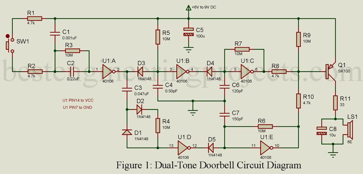
The secret to adjusting the tone frequencies lies in capacitors C6 and C7. These well-designed components allow you to fine-tune the auditory experience. They wield the power to shape the doorbell’s tone, making it uniquely yours. Notably, the discharge of these capacitors is cleverly managed by the parallel-connected R6 resistor, giving the circuit a brief pause of about 2 seconds before it’s ready for action again.
Incorporating this dual-tone doorbell circuit diagram into your space is like infusing a touch of nostalgia into your modern life. The ding-dong sound bridges the gap between tradition and contemporary design, making it a perfect addition to any home or workplace.
To embark on this creative journey, gather the components and follow the circuit diagram. Assemble everything carefully, and soon you’ll be rewarded with the delightful ding-dong melody whenever someone rings your doorbell. Embrace the fusion of technology and classic charm with your dual-tone doorbell circuit.
PARTS LIST OF DUAL-TONE DOORBELL CIRCUIT DIAGRAM
Resistors (all ¼-watt, ± 5% Carbon)
R1, R2, R8, R10 = 4.7 KΩ
R3, R4, R5, R6, R7, R9 = 10 MΩ
R11 = 33 Ω
Capacitors
C1 = 0.001 µF (Ceramic Disc)
C2 = 0.22 µF (Ceramic Disc)
C3, C4 = 0.047 µF (Ceramic Disc)
C5 = 100 µF/16V (Electrolytic Capacitor)
C6 = 120 pF (Ceramic Disc)
C7 = 150 pF (Ceramic Disc)
C8 = 10 µF/16V (Electrolytic Capacitor)
Semiconductors
IC1 = CD40106 (hex Schmitt-trigger inverter)
D1 – D5 = 1N4148 (Small signal fast switching diode)
T1 = SK100 (Medium power PNP Transistor)
Miscellaneous
SW1 = Push to on switch
LS1 = 8 Ω