The process of generating high-quality AM signals economically is greatly simplified by the availability of low-cost specialty linear integrated circuits (LIC). This is especially true for low-power systems, where low-level modulation schemes are attractive.
Linear Integrated Circuit Modulator using OTA
As an example, the RCA CA3080 operational transconductance amplifier (OTA) can be used to provide AM with an absolute minimum of design considerations. The OTA is similar to conventional operational amplifiers inasmuch as they employ the usual differential input terminals, but its output is best described in terms of the output current, rather than voltage, that it can supply. In addition, it contains an extra control terminal that enhances flexibility for use in a variety of applications, including AM generation.
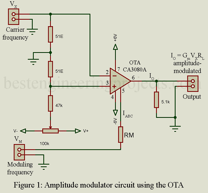
Figure 1 shows the CA3080 connected as an amplitude modulator. The gain of the OTA to the input carrier signal is controlled by the variation of the amplifier-bias current at pin 5 (IABC), because the OTA transconductance (and hence gain) is directly proportional to this current. The level of the unmodulated carrier output is determined by the quiescent IABC current, which is set by the value of RM. The 100-k potentiometer is adjusted to set the output voltage symmetrically about zero, thus nulling the effects of amplifier input offset voltage.
Linear Integrated Circuit Modulator using Programmable Dual Op-amp
Another linear Integrated circuit modulator is shown in Figure 2. This circuit uses an HA-2735 programmable dual op amp-half of it to generate the carrier frequency (A1) and the other half as the AM generator (A2).
In the HA-2735 op amp, the set current (pin 1 for A1 and pin 13 for A2) controls the frequency response and gain of each amplifier. This “programmable” function is unnecessary for the oscillator circuit, and thus Iset 1 is fixed by the 147-k resistor. Carriers up to about 2 MHz can be generated with A1.
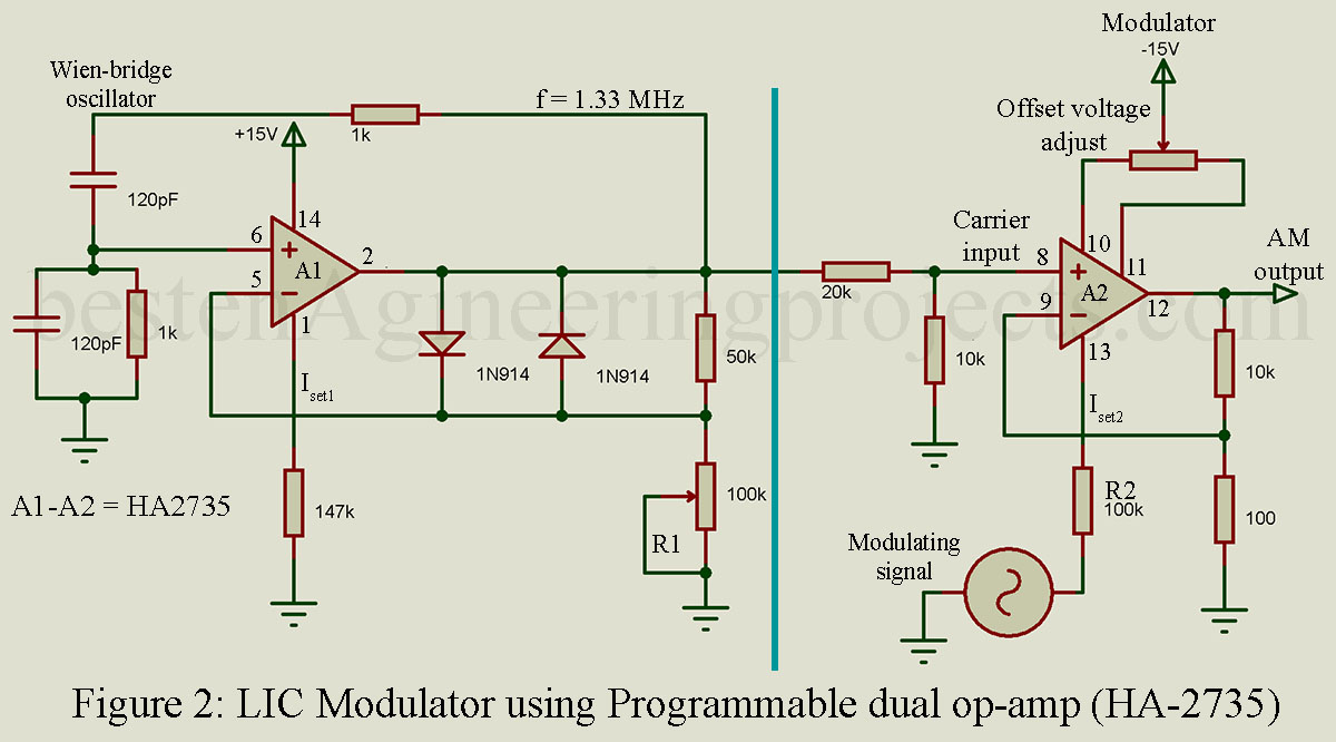
Amplifier A1 operates as a Wien-bridge oscillator. Amplitude control of the oscillator is achieved with 1N914 clamping diodes in the feedback network. If the output voltage tends to increase, the diodes offer more conductance, which lowers the gain. Resistor R1 is adjusted to minimize distortion and control the gain, and thus the amount of carrier applied to the modulator. With the components in Figure 2, the carrier frequency is approximately 1.33 MHz. This frequency can be changed by the selection of different RC combinations in the Wien-bridge feedback circuit (1 k and 120 pF).
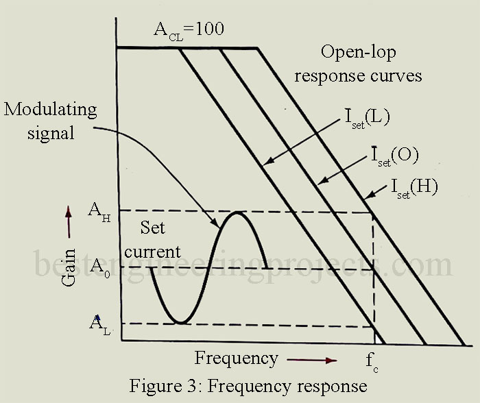
Amplifier A2‘s open-loop response is controlled by the modulating voltage applied to R2. The percentage of modulation is directly proportional to the modulating voltage. When sinusoidal modulation is applied to R2, the circuit gain varies from a maximum, АH, to a minimum, AL, as A2‘s frequency response to the carrier frequency, fc, is modulated by the set current [Figure 3]. This results in a very distortion-free AM output at pin 12 of A2. This circuit makes an ideal test generator for troubleshooting AM systems with carrier frequencies to 2 MHz. if a crystal oscillator were used instead of the Wien-bridge circuit, a high-quality AM transmitter could be fabricated with this AM generator.