Vital links of communication data flow over transmission lines daily. Phone conversations, computer data, and audio and video information all depends on the media’s ability to pass these signals wholly without any loss of quality. In this section, we will look at a problem encountered in the cabling application. Many opportunities exist today for the technician who can effectively track down and repair cabling troubles.
After completing this section, you should be able to
- Identify popular types of cabling available for LANs and other uses.
- Describe crosstalk interference and give an example of it.
- Describe simple methods for testing cable resistance, insulating, and TDR.
- Troubleshooting television antenna lines.
Common Application | Troubleshooting of Transmission Lines
A very common application of miles and miles of wire today is the local area network (LAN). The most popular kinds of wiring used to connect these systems are shielded and unshielded twisted pair (STP and UTP, respectively) and coaxial cable. STP and UTP represent about 50% to 70% of the installed base for LANs and coax about 30%. Twisted pair and coax are used mainly to connect the workstation to the hub, or punch-down block. The vitality of a local area network depends on the cabling base-the transmission media. As a matter of fact, 75% of LAN failure are wiring related. Therefore, technicians must learn techniques to effectively track cable problems and repair them.
Losses on Transmission Lines
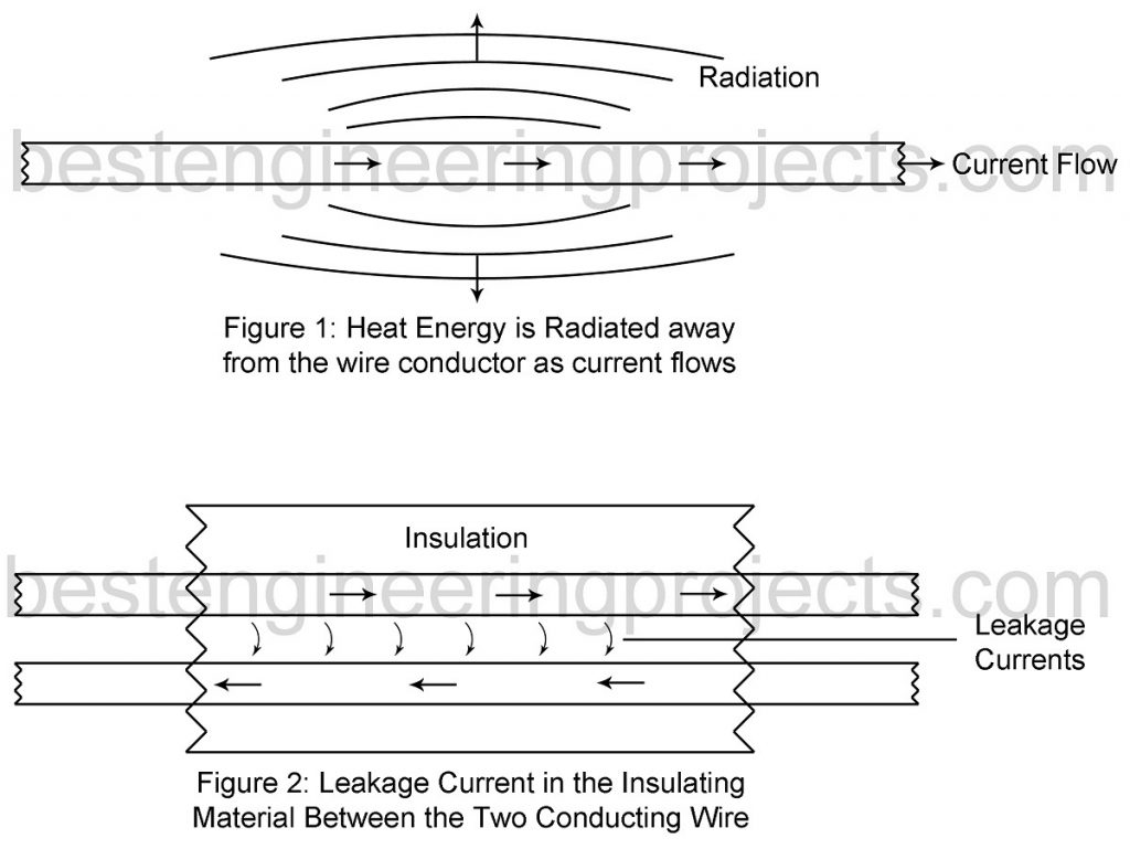
Transmission line losses can be summed up as energy losses, magnetic field losses, and electric field losses. Energy losses are a result of wiring heating and leakage currents in the dielectric material used as the insulator. Heat is produced when current flows in the wire that has resistance. The heat is radiated away from the wire as shown in figure 1. Figure 2 illustrated the effect of dielectric losses. Voltage potentials develop between the conductors that in turn cause minute currents to flow through the dielectric material. Heating and dielectric losses increase as signal frequency increases.
Magnetic field losses occur when currents are induced in a nearby conductor from the influence of another conductor’s magnetic field. Likewise, electrostatic fields tend to build a charge in a nearby conductor, causing electric field loss. Another effect of magnetic field and electrostatic field is induced, called crosstalk.
Interference on Transmission Lines
When UTP is used for the wire base in a LAN, there will be a transfer of energy between the wires, causing interference to be induced on wires. This unwanted coupling is caused by overlapping electric and magnetic field and is called crosstalk. All of us have experienced hearing another party’s conversation while having our own on the telephone. This is an example of crosstalk. Crosstalk can be reduced by careful attenuation to wire separation and twists. Tighter twist creates better coupling, which cancels the effects of magnetic and electrostatic fields, thus reducing crosstalk interference. Don’t untwist twisted pair, even at the connection points. Crosstalk can be measured by special hand-held instruments that directly compare the crosstalk reading against set standards. Crosstalk is also reduced by using STP or coaxial cable, but expense goes up and most be weighed against the system’s requirements.
Logic circuits can be fooled into creating data from noise. Noise can come from a variety of sources. Electric lights, electric generators, and switching devices generate noise that can become part of the signal if proper precautions are not observed. Do not run sensitive cabling near ac power lines or motors. Avoid running cable near overhead fluorescent lighting. In troubleshooting a system that is bothered by interference, check the wiring: someone may have ignored the above warning. Shielding and proper cable terminations are also safeguard against noise interference.
Cable Testing
Test instrument have been developed to do sophisticated testing on cable links. Discussing these instruments in detail is beyond the scope of this material. However, some instrument will be mentioned. Simple testing techniques can be used to discover faulty cabling. Pin-to-pin continuity testing done from one end of the wire to the opposite end is a simple effective means to detect miswiring and shorted and open link. Resistance measurement can be made on lengths of single wire and compared to the cable manufacturer’s specified resistance value. At the far end the wires to be tested would be shorted together, and the resistance would be measured at the near end. The resistance value would represent the resistance of two wires and must be taken under consideration. Resistance reading above or below the expected value indicates opens to shorts in the wires. Insulation tester or the megaohm meter (megometer) give a readout or audible indication of the insulation test result. Normally the megometer is connected to the wires at the near end, and the wires are disconnected at the opposite end. The readout represents the condition of the insulation. Breakdowns of the insulation at any point along the wiring path are readily displayed.
Television Antenna Line Repair
Transmission lines seldom totally fail without human intervention; however, they do age. Sunlight is hard on plastic dielectrics used in ribbon-type lines, sometimes called twin lead. Where twin-lead is used near salt water, it deteriorates more rapidly. Moisture and salt collect on the dielectric, causing the loss to rise to the point that the twin-lead is not usable.
Coaxial cables are relatively immune to aging due to weather. Older types suffered from communication due to plasticizer in the outer covering. Water has a very high dielectric constant and will change the characteristic impedance an increase the loss. Sometimes coaxial cable is installed with very tight turns around corners. Over time, the center conductor will walk through the dielectric and eventually short the cable.
Suppose you are called to service a television receiver with “snow” almost overwhelming the picture. TV twin-lead is being used and is too cheap to justify much testing. Simply inspect it, looking for crack in the plastic and discoloration of the plastic. You might take the time to short the far end and check the resistance with an ohmmeter, there should be almost no resistance. If the far end is open, the resistance should be infinite. When in doubt, change the twin-lead.