A good high-power laboratory power supply must-have device for electronic enthusiasm. As being electronic enthusiastic we all love to design our own bench power supply. So here in this article, you will learn to design your own variable current and voltage 10A laboratory power supply circuit.
Features of 10A Laboratory Power Supply Circuit:
- Users can select voltage and current as per the requirement
- Constant current mode
- Short circuit indication and protection
- Voltmeter and ammeter
- Fuse for extra protection
Applications
- It can be used as a general variable power supply.
- It can be used for troubleshooting electronic boards like tracing or locating shortcircuit.
- It can produce a minimum of 0.8V output to a maximum of 31.5V. So it can be used to power devices.
Description of 10A laboratory power supply circuit
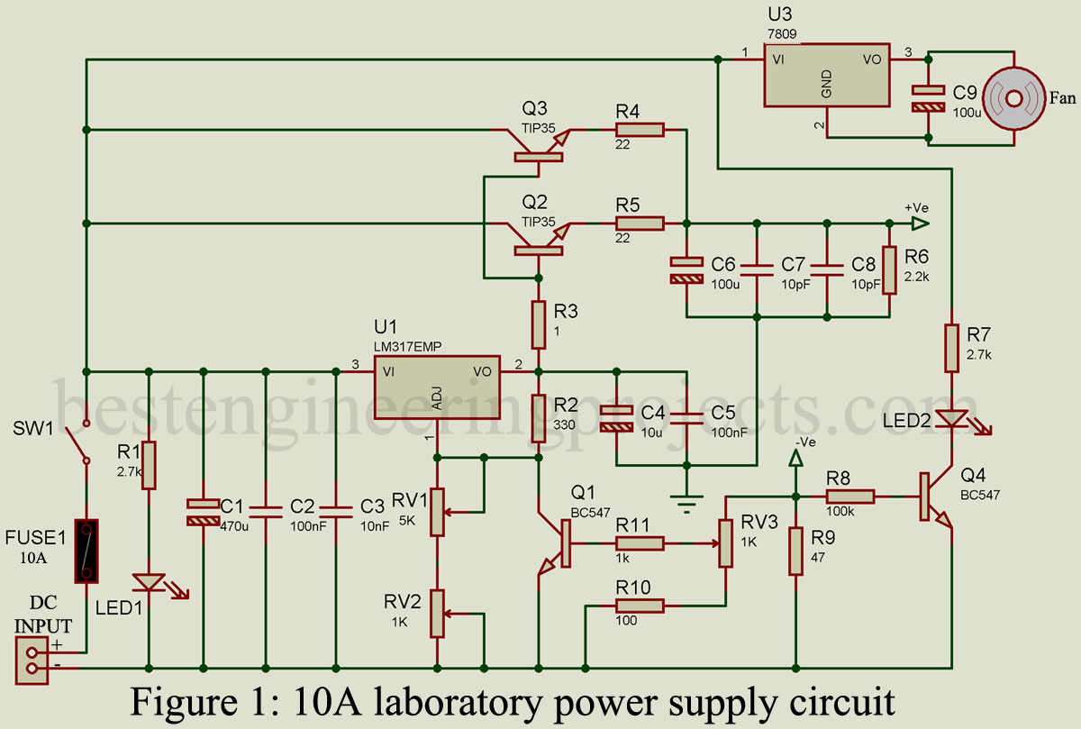
The circuit of the high-power bench power supply is shown in Figure 1. The circuit does not include a power source in the design. You can use SMPS or power supply devices of an old electronic device. The circuit diagram is quite simple and self-explanatory.
Voltage Regulation section
The voltage regulation section is designed around LM317 IC. LM317 is a variable voltage regulator IC that provides great regulation. It needs a few components like a resistor in order to operate. A feedback resistor is connected to the output terminal and adjustment wiper of variable resistor VR1, where the fixed terminal is connected to the ground through another resistor as shown in the circuit diagram. The value of these resistors is responsible for voltage output.
For a proper description and resistor value selection of variable or adjustable voltage regulator, please go through “Adjustable output voltage regulator”. After completing this article you will be able to design your own variable voltage power supply.
High Current Section:
As LM317 can only handle current up to 1A, thus a power transistor TIP35C is used here. It can handle up to 100V with a max power of 125W and a max current of 25A. For flawlessly working two TIP35C power transistor is used. These two power transistors are connected in parallel where the base is connected to the output of LM317 through a resistor R3. Resistors are connected to each emitter terminal of transistors T3 and T4 in order to compensate for conduction differences.
The two variable resistors are connected to the adjustment pin if Lm317 (U1). Variable resistor RV1 is used as a coarse adjustment of voltage and variable resistor RV2 is used as a fine adjustment of voltage. Variable resistor RV3 is used to adjust the output current. Output is obtained from +Ve and -Ve terminals.
Constant current circuit:
The resistor R9 is a current sensor. When a high current is drawn or short-circuited voltage drops at the resistor R9 also increased. This voltage is large enough to provide the required base voltage at transistors base Q1 and Q4. This base voltage turn transistor Q1 ON, which short adj. terminal of LM317 (pin 1) to the ground. When the adj. terminal is shorted to ground it works as a constant current source. At the same instance, Q3 also starts to conduct and LED2 starts to glow indicating a short circuit.
Voltage regulator IC 7809 (U2) is used to power a 9V DC fan. This fan is used to dissipate the heat and must be mounted on the heat sink.
A good heat sink is required for a power transistor.
Component Required
| Resistor (all ¼-watt, ± 5% Carbon) |
| R1, R7 = 2.7 KΩ
R2 = 330 Ω R3 = 1 Ω R4, R5 = 22 Ω/5W R6 = 2.2 KΩ R8 = 100 KΩ R9 = 47 Ω / 10W R10 = 100 Ω R11 = 1 KΩ RV1 = 5 KΩ RV2, RV3 = 1 KΩ |
| Capacitors |
| C1 = 470 µF/63V
C2, C5 = 100 nF C3 = 10 nF C4 = 10 µF/50V C6, C9 = 100 µF/50V C7, C8 = 10 pF |
| Semiconductors |
| Q1, Q4 = BC547
Q2, Q3 = TIP35 U1 = LM317 U2 = LM7809 LED1 = 5mm RED color LED LED2 = 5mm YELLOW color LED |
| Miscellaneous |
| F1 = 10 Amp. Fuse
Heat sink for TIP35 9V DC Fan ON/OFF Switch |
Hello: What is the maximum value of the input voltage? And the current? Assuming it delivers 10 amps. Thanks
For 10 Amps to flow through a 47 Ohm resistor it would surely require a potential higher than 31.5 Volts or has Ohms law been wrong all along.
Si van a fluir 10 amperes por R9 de 47 ohms y aplicando la ley de Ohm donde W=I x I x R, o sea W=10x10x47 =4.700 watts ,una locura.Algo está mal en el diseño o en los valores expresados.