A precision voltage reference provides a constant, stable output voltage under a wide range of line, load, and temperature conditions. These devices usually work on the principle of bandgap voltage. Voltage drops are produced across two transistor base emitter diodes with unequal current flow. These voltage drops exhibit a negative temperature coefficient (the drop decreases as temperature is increased).
However, the difference between the two voltage drops exhibits a positive temperature coefficient. When properly combined to equal a sum of 1.23V (the bandgap voltage), a near zero temperature coefficient is obtained. This voltage forms the basic of a wide variety of precision voltage references. If a voltage greater than 1.23V is desired, the bandgap voltage is amplified. If a laser voltage is desired, the bandpass voltage is reduced through a precision voltage divider. Some devices have on chip heaters (large semiconductors designed to maintained a constant on chip temperature for extra stability), trimming features, and programmability.
Key Parameters of Precision Voltage Reference Circuit
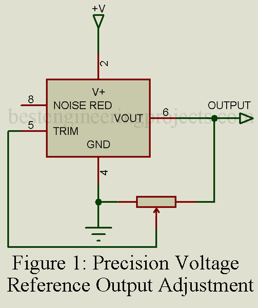
Output adjustment range. The output voltage of a reference can be adjusted with an external potentiometer. This specification is given as a percentage of output voltage 3.3% is typical.
Output temperature coefficient. This is the ratio of output voltage change with temperature variation. This specification is expressed in ppm/0C, with 10 ppm/0C being a typical value.
Line Regulation. This parameter specifies the change in output voltage due to a change in the input (line) voltage.
Load regulation. This parameter specifies the change in output voltage due to a change in load (current demand).
Applications of Precision Voltage Reference Circuit
Precision voltage references are used as calibration standards and precision current sources. They are used in equipment such as power supplies, regulators, high/low voltage sensors, and panel meters.
10V Precision Voltage Reference Circuit
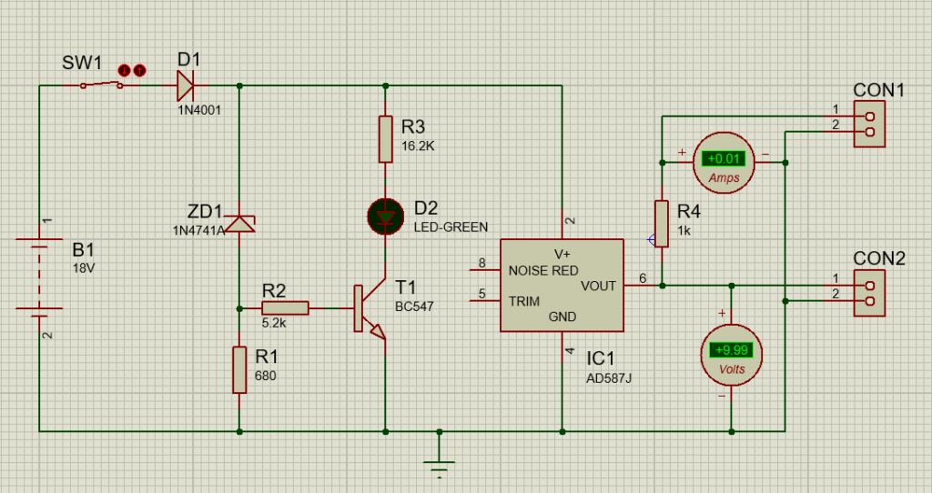
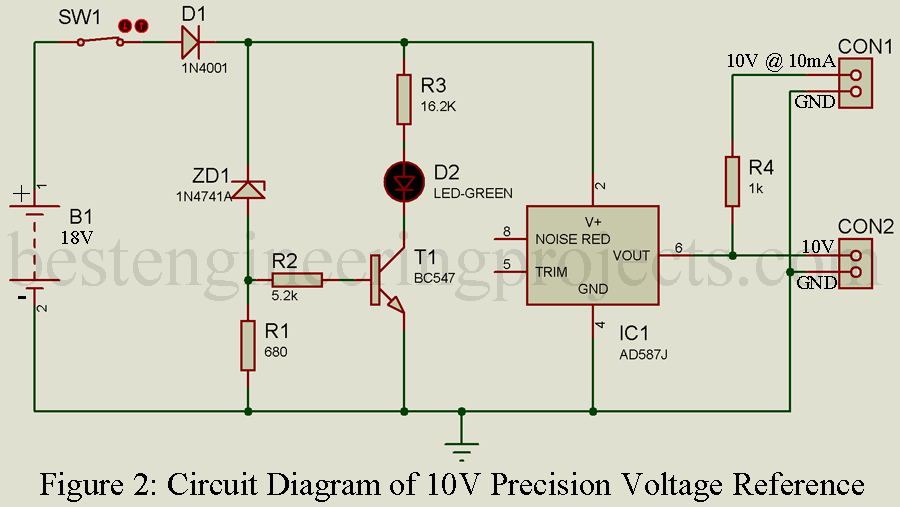
Let’s see a simple 10V precision voltage reference circuit designed around AD587 IC. The circuit diagram of 10V precision voltage reference is shown in figure 2. It has two distinct output i.e. 10.000V and 10.000V @ 10mA as shown in simulation circuit.
18V DC supply (two 9v battery connected in series) given to the input of the circuit. Diode D1 is used here in order to provide reverse voltage protection, it will protect the circuit when battery or power supply is connected incorrectly.
One Zener diode 1N4741 is used here which conduct only if it get reverse voltage greater than 11V. One current limiting resistor is connected in series with zener diode as shown in circuit diagram. This resistor not only protect the zener diode but also provide the voltage drop which help to switch the transistor T1.
Voltage drop across 600-ohm resistor (R1) = Power supply voltage – zener diode
If the supply voltage = 18V,
Then, voltage drop across 680-ohm = 18V-11V = 7V.
This voltage is responsible for switching the transistor T1. Base to emitter of NPN transistor is basically a diode which start to conduct when voltage exceed 0.6V. So, if the voltage of base emitter junction exceeds 0.6V then the transistor starts to conduct. One current limiting resistor of 5.2K-Ohm is used here in order to protect the transistor from current.

The conduction of transistor T1 provides the path for voltage to flow through LED1 to ground and hence LED1 illuminates. Here, LED1 is used to indicate the voltage and illuminate till it get required voltage. One current limiting resistor of 16.2K-Ohm is connected in series of LED1 from extra voltage and current.
When transistor T1 conduct, LED1 start to illuminate. So, let’s calculate upto what voltage from power supply transistor conducts.
Required transistor base to emitter volt = 0.6V
Diode conducting voltage = 0.6V
Zener diode voltage = 11V
Therefor, required voltage to turn the LED or drive transistor = 0.6V + 0.6V + 11V = 12.2V. When this circuit get voltage greater then 12.2V LED1 will illuminate as shown in simulation circuit (Figure 3).
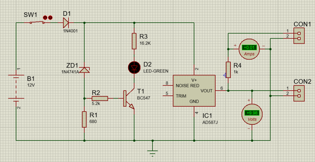
LED1 illuminate or transistor T1 conduct till the power supply provide voltage greater than 12.2V. If it fails to provide voltage less then 12.2V LED1 fail to illuminate as shown in simulation circuit (figure 4). When we give 12V LED supply, LED fail to illuminate and its time to replace the battery.

Component Required for 10V Precision Voltage Reference Circuit.
| Resistor (all ¼-watt, ± 5% Carbon Unless Stated Otherwise) |
| R1 = 680 Ω
R2 = 5.2 KΩ R3 = 16.2 KΩ R4 = 1 KΩ, 1% tolerance |
| Semiconductors |
| IC1 = AD587J
D1 = 1N4001 ZD1 = 1N4741A Zener Diode T1 = BC547 LED1 = Green color LED |
| Miscellaneous |
| SW1 = ON/OFF Switch
CON1, CON2 = Two connectors Two 9V Battery |

