In the tutorial Arduino MOSFET LED driver circuit, you will learn to make your MOSFET Driver for any higher power appliance like LED Strip, high power DC motor, etc. We all know that we need a driver circuit to control high-power appliances like DC motors, electrical appliances, etc. So, here we are using MOSFET to control the operation of the LED strip.
If you want to know more about MOSFET, its type, Symbol, application, and characteristic curve please do read the previous article on MOSFET | Types of MOSFET | Circuit Symbol.
Component Required for Arduino MOSFET LED Driver Circuit
Arduino UNO Board x 1
IRFZ44N MOSFET x 3
5.6K resistor x 3
12V, 2A power supply adapter
Circuit Description of Arduino MOSFET LED Driver Circuit
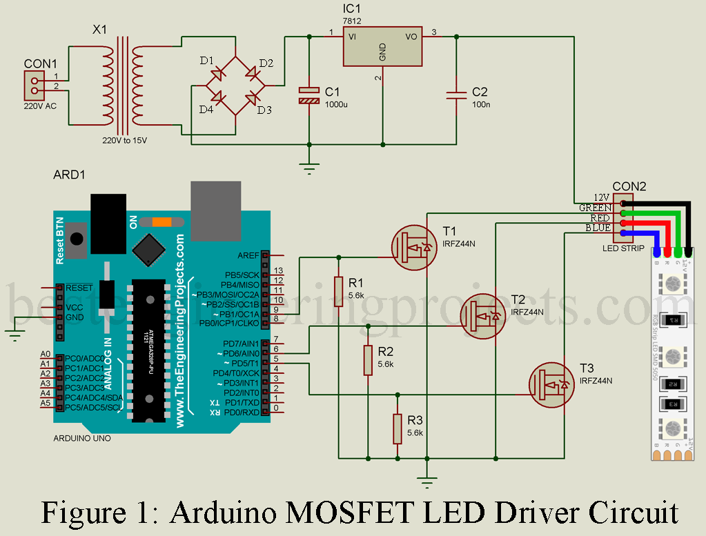
The circuit is shown in figure 1, built around the Arduino uno board, MOSFET, and a few other components. The circuit is divided into two main sections i.e. Power Supply Unit and Control Unit.
Power Supply Unit
The power supply circuit is designed using a step-down transformer and a 12V fixed voltage regulator. The input from AC mains is given to the primary side of the transformer, and 15V AC is available on the secondary side. This 15V AC is rectified using a bridge rectifier designed around four rectifier diodes. This rectified DC is filtered using high-value electrolytic capacitor C1 (1000 uF) and given to the input of 12V series voltage regulator IC (MC7812ACTG). 12V at 2A is available at the output pin of 7812 which is given to the power supply pin of the LED strip.
X1 = 220V to 15V, 2A secondary transformer
D1 – D4 = 1N4007
C1 = 1000 uF, 25V (electrolytic capacitor)
C2 = 100nF (Ceramic Capacitor)
IC1 = MC7812ACTG
Note: You can also use a 12V, 2A adapter for the power supply. Here, in this project we are using a 12V, 2A power supply adapter.
Control and Driver Circuit:
The control circuit is designed around the Arduino uno board. Here, we are using three PWM pins of Arduino board (pin 5, 6, and 9 but you can use any PWM pin). We are using PWM pins instead of a normal digital pin because MOSFET is a voltage control device i.e. the voltage at the gate (G) determines the conduction level. PWM pin can supply different voltages from the range of 0V to 5V in 255 steps. This is required for the feeding effect of LED.
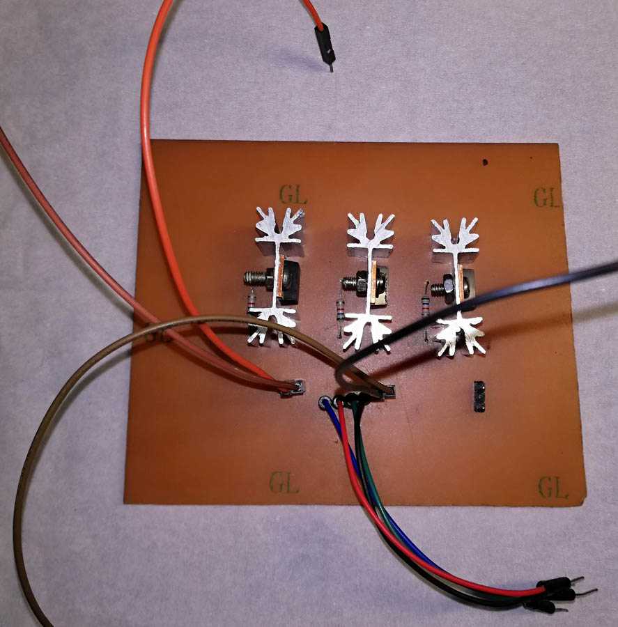
Figure 2: PCB For MOSFET LED Driver
The driver circuit is designed around three MOSFETs for three different LEDs (RED, GREEN, and BLUE). Arduino pin 5, 6, and 9 is connected to these three MOSFET gate as shown in the circuit diagram. Three individual resistors each of 5.6K ground the gate pin of all these MOSFETs. The source pin (S) of all these MOSFETs is grounded where the drain pin of each MOSFET is connected to a different LED as shown in a circuit diagram.
 Figure 3: Author Prototype for Arduino MOSFET LED Driver Circuit
PCB Diagram: The PCB diagram is designed using Proteus 8.1. The PCB diagram shown here is only for the MOSFET driver unit. The solder side and component side PCB as shown in the figure below is scaled by 200%. You can download an accurate size PCB diagram in PDF format from the link below.
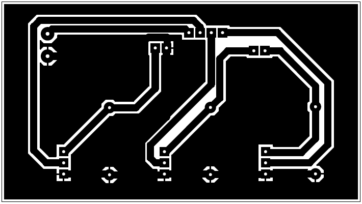 Figure 4: Solder Side PCB for LED Strip Driver
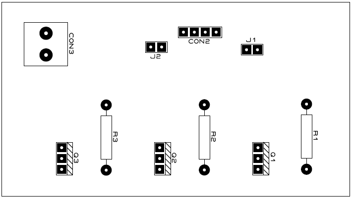 Figure 5: Component Side PCB for LED Strip Driver
CLICK HERE TO DOWNLOAD PCB DIAGRAM
Software Code: Software code is written in Arduino programming and compiled using Arduino IDE. The code is very simple, the main purpose of this code is to supply varying gate voltage. You can directly download the code and modify it according to your requirement.
|
1 2 3 4 5 6 7 8 9 10 11 12 13 14 15 16 17 18 19 20 21 22 23 24 25 26 27 28 29 30 31 32 33 34 35 36 37 38 39 40 41 42 43 44 45 46 47 48 49 |
int brightness = 255; //Max brightness of led //individual brightness values for the red, green and blue LEDs int gBright = 0; int rBright = 0; int bBright = 0; int fadeSpeed = 10; #define RED_LED 6 #define BLUE_LED 9 #define GREEN_LED 5 void setup() { // initialize PWM pin for LED output pinMode(GREEN_LED, OUTPUT); pinMode(RED_LED, OUTPUT); pinMode(BLUE_LED, OUTPUT); } // the loop function runs over and over again forever void loop() { digitalWrite(GREEN_LED, HIGH); // turn the Green LED on at maximum digitalWrite(RED_LED, HIGH); // turn the Red LED on at maximum digitalWrite(BLUE_LED, HIGH); // turn the Blue LED on at maximum delay(5000); // wait for 5 seconds digitalWrite(GREEN_LED, LOW); // turn the Green LED off by making the voltage LOW digitalWrite(RED_LED, LOW); // turn the Red LED off by making the voltage LOW digitalWrite(BLUE_LED, LOW);// turn the Blue LED off by making the voltage LOW // loop to glow the LED with fade speed for (int i=0;i<256; i++){ analogWrite(RED_LED, rBright); rBright +=1; delay(fadeSpeed); } for (int i=0;i<256; i++){ analogWrite(BLUE_LED, bBright); bBright += 1; delay(fadeSpeed); } for (int i=0;i<256; i++){ analogWrite(GREEN_LED, gBright); gBright +=1; delay(fadeSpeed); } } |