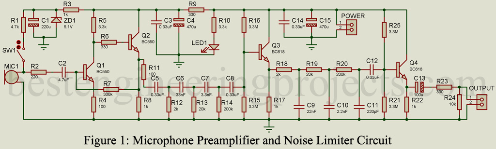
The circuit posted here is of a microphone preamplifier and noise limiter. The main role of a microphone preamplifier circuit is to raise the signal level of the microphone output signal. A microphone is a transducer that converts sound signals to electrical signals. The output signal of the microphone is very small in a range of a few millivolts. This signal needs some level of amplification before the power amplification. Generally, the gain of the preamplifier is set to between 30 to 100. Besides pre-amplification, the circuit also limits noise. The noise can be reduced by limiting the bandwidth of the signal from 200-300Hz to around 3.3kHz – 5kHz
Circuit description Microphone Preamplifier and Noise Limiter
The circuit is divided into three main sections:
- preamplifier
- High pass filter
- Low pass filter
Preamplifier
The preamplifier is designed around two-transistor T1 and T2. The output of the microphone is given to the base of transistor T1 through an RC coupled network. The output from the collector of the transistor T1 is given to the base of transistor T2.
Gain of preamplifier
The overall gain of the preamplifier section is determined by two resistors R4 and R5. The gain is approx equal to -R5/R4.
Let the value of resistor R4 = 100-ohm and resistor R5 = 3.3K then gain = 33.
The overall current of the preamplifier is determined by resistor R7.
High pass Filter
A high pass filter circuit is designed to limit the bandwidth of the signal to around 200Hz – 300Hz. It consists of three RC networks as shown in the circuit diagram
The formula of cut off frequency is  . By using this formula cut-off frequency of high pass and low pass can be calculated.


From the above calculation, we can say that high pass cut-off frequency 
The value of resistor and capacitor can be selected according to the desired cut-off frequency of the high pass filter.
Low pass filter
A low pass filter circuit is designed to limit the bandwidth of the signal to around 3.3kHz – 5kHz. It also consists of three RC networks.


 .
.
From the above calculation, we can say that low pass cut-off frequency  .
.
Power supply: Preferred power supply will be above 15V but can work on as low as a 9V supply.
Component Required for Microphone Preamplifier and Noise Limiter
| Resistor (all ¼-watt, ± 5% Carbon) |
| R1 = 4.7 KΩ
R2 = 220Ω R3, R8, R17, R22 = 1 KΩ R4, R11 = 100 Ω R5, R10 = 3.3 KΩ R6, R9, R23 = 330 Ω R7 = 330 KΩ R12, R18 = 2 KΩ R13, R19 = 20 KΩ R14, R20 = 200 KΩ R15, R16, R21, R25 = 3.3 MΩ R24 = 10 KΩ |
| Capacitors |
| C1 = 220 µF/ 25V
C2 = 4.7 nF C3, C5, C8, C12, C14 = 0.33 µF C4, C11 = 470 µF/25V C6 = 33 nF C7 = 3.3 nF C9 = 22 nF C10 = 2.2 nF C11 = 0.22 nF C13 = 100 µF/25V |
| Semiconductors |
| Q1, Q2 = BC550
Q3, Q4 = BC618 ZD1 = 5.1V Zener diode LED1 = 5mm RED Color LED |
| Miscellaneous |
| SW1 = ON/OFF Switch
MIC1 = Microphone |