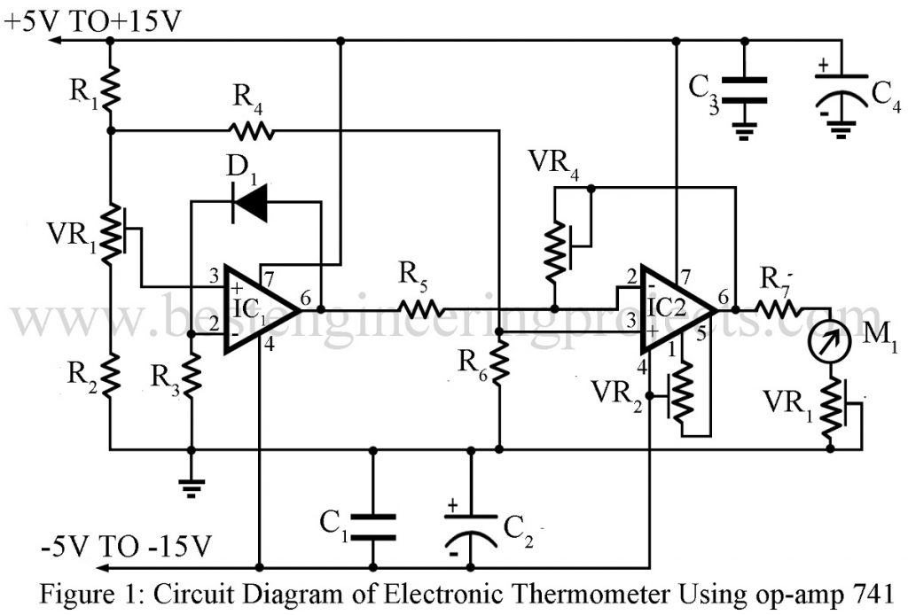
Here is the circuit diagram of an electronics thermometer using op-amp 741 IC and a silicon diode having a range of -20oC to 125oC. Various types of temperature measuring and controlling circuits either using a microcontroller or discrete component are already posted on bestengineeringprojects.com.
Circuit Diagram of Electric Thermometer Using OP-AMP 741
The entire circuit of the electric thermometer is built around two op-amp 741 IC, a silicon diode, and a few passive components, where silicon diode D1 is used as a temperature sensor. The diode 4148 has a voltage drop of 0.7V at room temperature and has a linear characteristic as the voltage change is very small (2mV/oC with an increase in temperature) over a wide range of temperatures. Linear characteristics of the sensor diode eventually eliminate the problem of scale calibration.
The working of this electronic thermometer can be understood in two phases:
Phase-I of Electronics Thermometer Using Op-amp 741 IC
Here, the op-amp IC1 works as a temperature-to-voltage converter whereas sensor diode D1 provides a feedback path. Thus, the output of the op-amp depends upon the voltage across the diode which eventually depends on the temperature. The non-inverting pin of op-amp IC1 is maintained at a constant voltage by VR1, R1, and R2.
Phase-II of Electronics Thermometer Using Op-amp 741 IC
The output of the 1st op-amp (IC1) is connected to the input of the 2nd op-amp (IC2) which works as a voltage amplifier. Gain is adjusted by VR4 in such a way that the voltage change of 2mv at pin 2 of IC2 causes an increase of 10mV at the output. The output is observed at the analog meter and VR3 adjusts its sensitivity. Meter readings can be adjusted by keeping the diode at various known temperatures.
Check out other Electronics Thermometer and Temperature related circuits posted in bestengineeringprojects.com
- Electronic Thermometer Circuit
- Electronic Room Thermometer Using Op-amp 741
- PIC16F73 Based Temperature Indicator and Controller
- Dynamic Temperature Indicator and Controller Using Arduino
PARTS LIST OF ELECTRIC THERMOMETER USING 741 IC
| Resistor (all ¼-watt, ± 5% Carbon) |
| R1 = 650 Ω
R2 – R5 = 1 KΩ R6 = 6.8 KΩ R7 = 10 KΩ VR1 = 2.2 KΩ VR2 – VR4 = 10 KΩ |
| Capacitors |
| C1 = 0.1 µF (Ceramic Disc)
C2 = 10 µF,16V (Electrolytic Capacitor) C3 = 0.1 µF (Ceramic Disc) C4 = 10 µF,16V (Electrolytic Capacitor) |
| Semiconductors |
| IC1, IC2 = 741 (Operational Amplifier)
D1 = 1N4148 (Silicon Switching Diode) |
| Miscellaneous |
| Analog ammeter(0-1mA) |
Check out other top popular Articles :
Clock Signal Generator Circuit

can you tell us what is VR in the circuit
VR is a variable resistor or potentiometer.