Almost all pre-amplifier circuit uses ordinary op-amp, which is not as good as JFET op-amp. JFET op-amp has very low noise and a very high input impedance due to which they can be used in a large number of circuits. The circuits are shown here fulfill the need for a handy, high-performance simple control preamp.
Circuit Description of JFET Op-Amp Based Stereo Control Preamp
Based on LF353N bi-FET op-amp the circuit is ideal for the stereo application for which quad LF347 or four LF351s can also be used is shown in figure 1.
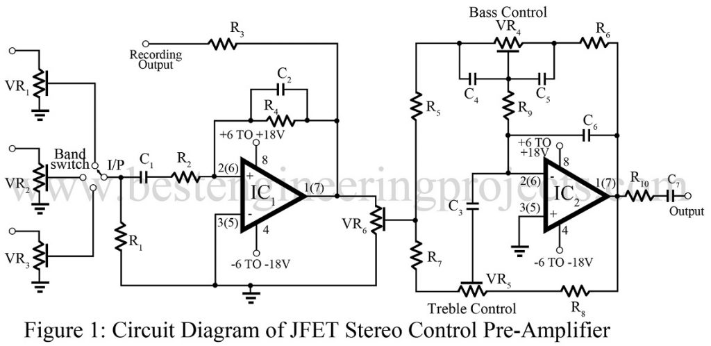
Input from tuner or aux. is fed to inverting amplifier with a gain of about 20. Input impedance is fairly high and a 10pF capacitor provides the band imitating fiction.
Gain can be reduced or increased by changing the value of 22kΩ but within limits as more gain means more distortion. The output is fed to volume control VR6 which feeds the tone control stage based on IC2. Output is taken via a 22kΩ resistor. A 10 µF capacitor can be added if the power amp does not have an input coupling capacitor.
It can be used with any power amplifier. Use of shielded cable is recommended. Well filtered supply is required, which can also be obtained from the existing supply by using the voltage divider. For best results, control pots should be mounted on the PCB itself.
The voltage of the power supply should be ±6V to ±18V. But it is recommended that it should be as high as possible so that input signal voltage of larger magnitude can be recommended. In case LF series devices are not available, TL071/72 can be used. The use of separate volume control is recommended. To enable switching between tuner, aux. etc, a preset of 100kΩ can be used in each input to set the level by a single band-switch.
PARTS LIST OF JFET OP-AMP BASED STEREO CONTROL PRE-AMPLIFIER
| Resistor (all ¼-watt, ± 5% Carbon) |
| R1, R3 = 470 KΩ
R2 = 1.2 KΩ R4 = 22 KΩ R5 – R8, R10 = 2.2 KΩ R9 = 15 KΩ VR1 – VR3 = 100 KΩ VR4, VR5 = 47 KΩ VR6 = 4.7 KΩ |
| Capacitors |
| C1, C7 = 10 µF (Electrolytic Capacitor)
C2 = 10 pF (Ceramic Disc) C3 = 4.7 nF (Ceramic Disc) C4, C5 = 68 nF (Ceramic Disc) C6 = 47 pF (Ceramic Disc) |
| Semiconductors |
| IC1, IC2 = LF353 ( low-cost, high-speed, JFET-input operational amplifier) |