PIC16F73 Based Temperature Indicator and Controller
A normal thermometer gives an indication of the temperature. Focus on the fact ‘indication’, i.e. it only reads and displays the reading. Using this property, here we have presented a standalone digital thermometer that also controls the temperature of the heating element of a device according to its requirement, along with the temperature reading function. In order to transform our logic into practical implementation, we took the help of a Microcontroller (PIC16F73) which ensures dynamic and faster control.
Additional components like temperature-controller knob and liquid crystal display (LCD) are included to make the system user-friendly. The sensed and set temperature values are simultaneously displayed on the LCD panel on the Kelvin scale.
The circuit “PIC16F73 Based Temperature Indicator and Controller” is programmed for ‘on’/’off’ control of temperature. With the use of fewer components, the circuit is compact which aids in easy installation. It can be implemented for several applications including air-conditioners, water-heaters, snow-melters, ovens, heat-exchangers, mixers, furnaces, incubators, thermal baths, veterinary operating tables and much more. It is no doubt that the PIC16F73 microcontroller is the heart of the circuit as it controls all the functions.
Circuit Description of PIC16F73 Based Temperature Indicator and Controller:-
The functional block diagram of the microcontroller PIC16F73 based Temperature Indicator and controller is depicted in figure 1. Here, the temperature transducer (AD590) senses the temperature and converts it into an – electrical signal, which is applied to the microcontroller. The analogue signal is converted into digital format by the inbuilt analogue-to-digital converter (ADC) of the microcontroller. The sensed and set values of the temperature are displayed on the 16×2-line LCD. Using the electromagnetic relay, the microcontroller drives a transistor to control the heating element.
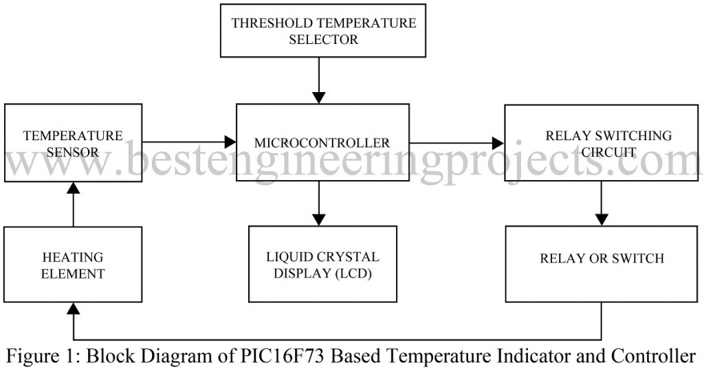
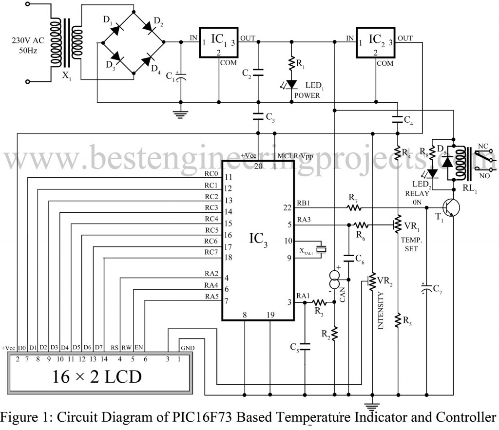
The overall embedded system design is simplified using the inbuilt ADC by providing a direct interface for temperature, pressure, motion and other sensors. The external knob fitted on the front panel can be used to vary the set temperature value from 253 ° K to 430 °K which extends the system flexibility. Fig. 2 shows the actual circuit of PIC16F73 based temperature indicator and controller. The temperature sensor (AD590) outputs a current of 1 uA/ °K.
For a supply volt age between 4V and 30V, a high-impedance constant current is delivered. The sensing range of the temperature sensor is linear from 218 °K (–55 °C) to 423 °K(+150 °C). The current from the sensor is converted into voltage with a sensitivity of 1V/0K (1 uA/0K x 1000) by the 10-kilo-ohm resistor. Hence, the voltage range is 2.18V to 4.23V. This voltage is then fed to pin 3 (RA1) of the microcontroller.
Two port-A pins of the microcontroller; pins 3 (RA1) and 5 (RA3) are programmed as analogue inputs. The analogue input signal is converted into 8-bit digital equivalent output by the inbuilt 8-bit ADC. The analogue reference voltage can be selected from the software; either the positive supply voltage of the device (Vcc) or the voltage level of the RA3 pin. In the circuit, Vcc (5V) is chosen as the analogue reference voltage.
Pins 3 (RA1) and 5 (RA3) are programmed so as to sense the analogue voltages corresponding to the sensed and set temperature values, respectively. The voltage corresponding to the set temperature is obtained by means of a potential divider network comprising a potentiometer (VR1) and two fixed resistors (R4 and R5). The variable terminal of the potentiometer is connected to pin 5 (RA3) of the microcontroller and the shaft is rotated by the user to vary the set-point temperature that is visible on the LCD.
The microcontroller has been so programmed that it senses the analogue voltages corresponding to the sensed and set temperature values. The sensed voltages are manipulated such that the corresponding temperature values are displayed on the LCD by sending out the corresponding data signals through pins 11 through 18 (RC0 through RC7) and control signals through pins 4, 6 and 7 (RA2, RA4 and RA5) of the microcontroller. The sensed temperature value thus obtained is compared with the set-point temperature value. Pin 22 (RB1) of the microcontroller goes high if the set-point temperature is higher than the sensed temperature. This pin has been programmed as an output to control the relay through transistor T1. The relay contacts are connected to the heating element.
Data is sent to the LCD’s data pins 7 through 14, Control signals required before each data transmission are sent to pins 4, 5 and 6 (RS, R/W and Enable) of the LCD.
Working of the Circuit PIC16F73 Based Temperature Indicator and Controller:-
The step-down transformer X1 supplies a secondary output of 7.5V-0-7.5V AC, 250 mA from the main supply. A full-wave rectifier comprising diodes D1 through D4 is used to rectify the transformer output which is then filtered by capacitor C1. ICs 7812(IC1) and 7805 (IC2) are included to provide regulated 12V and 5V power supplies. Capacitors C2 and C4 bypass any ripple in the regulated outputs. LED1 gives a power-on indication when current flows through resistor R1.
The temperature sensor is connected to the output of IC2 (Voltage regulator IC) for the power supply, where its terminals (‘+’, ‘-‘ and ‘CAN’) is connected as shown in the circuit diagram. Among them, the ‘+’ terminal is connected to the 12V power supply and the ‘CAN’ terminal is grounded where resistor R2 is used to convert a current of the ‘-‘ terminal into a voltage of the temperature sensor. The voltage obtained from the ‘-‘ pin is then applied to pin 3 (RA1) of the microcontroller.
The four resistors with potentiometer and resistor R5 combinedly form a potential divider and is connected across 5V supply. The variable terminal of the potentiometer VR1 is connected to pin 5 of the microcontroller. For noise filtering, we use three capacitors (C5 to C7). For clock frequency, a 5 MHz crystal oscillator is connected to pin 9 and 10 of the Microcontroller.
The relay is connected between +12V and the collector of transistor T1. When pin number 22 of the microcontroller is high, transistor T1 saturates which in return energizes the relay to switch the device ‘on’. In case when pin 22 constitutes a low signal, transistor T1 cuts off and then the relay de-energises to turn the device ‘off’. In this circuit, diode D5 is used as a free-wheeling diode.
PARTS LIST OF PIC16F73 BASED TEMPERATURE INDICATOR AND CONTROLLER
| Resistors (all ¼-watt, ± 5% Carbon unless stated otherwise) |
| R1, R8 = 1 KΩ R2, R3, R6, R7 = 10 KΩ R4 = 3.9 KΩ R5 = 15 KΩ VR1 = 10 KΩ VR2 = 10 KΩ |
| Capacitors |
| C1 = 1000 µF, 35V (Electrolytic Capacitor) C2, C3 – C6 = 0.33 µF (Ceramic Disc) C7 = 100 µF, 100V (Electrolytic Capacitor) |
| Semiconductors |
| IC1 = LM7812 (12V Series Fixed Voltage Regulator) IC2 = LM7805 (5V Series Fixed Voltage Regulator) IC3 = PIC16F73 (Microcontroller) T1 = SL100 (medium power NPN general purpose transistor) D1 – D5 = 1N4007 (Rectifier Diode) AD590 = Temperature Sensor LED1 = Red LED LED2 = Green LED LCD1 = 16*2-line LCD |
| Miscellaneous |
| X1 = 230V AC Primary to 7.5V-0-7.5V, 250mA secondary transformer XTAL = 5 MHz crystal RL1 = 12V, 200, 1C/O relay SW1 = ON/OFF Switch |