Introduction to Monitoring System using AT89C51: Intercoms and calling bells fit properly only in the luxurious hotels, lodges, and high-class buildings. In small vicinities like small hotels, offices, and clinics, these are not the correct options to choose for communication between the working/assisting staff and people. It is all because of the cost and the fact that this provision can be made for a limited number of points. Here’s a simple and economical room-monitoring system that provides audio-visual identification of the call point. In addition to this, the system also provides feedback to the caller (in the form of a busy signal). Using minimal hardware and software, this project offers a clean and easy way to communicate.
Circuit Description of Monitoring System using At89c51
From the circuit diagram, it is clear that the heart of the circuit is microcontroller IC AT89C51 (IC1) which is usually the common component when we talk about microcontroller-based projects. In this particular project, two ports: 0 and 2 of the microcontroller are used in output mode for the seven-segment display and LEDs. Similarly, port 1 is set in input mode to receive input signals from the switches. The overall configuration is depicted clearly in the figure below.
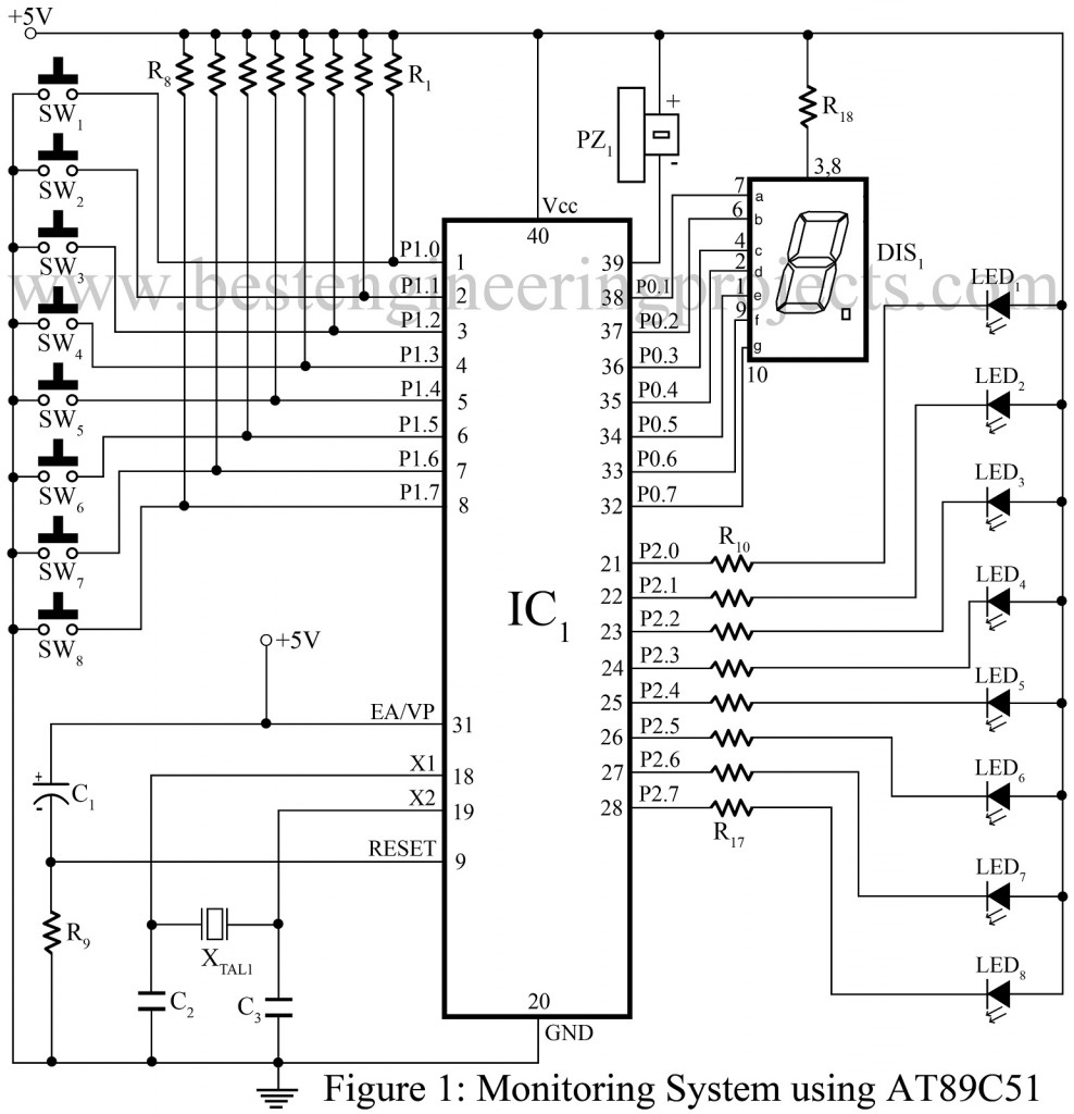
Seven-segment display, switches, few LEDs, piezo-buzzer, and passive components are the key elements of this circuit along with the IC. Once the connection is set up, the circuit is ready for installment. In doing so, one must fix the switches and their respective LEDs in eight different rooms enabling the person to make a request when the system is not busy responding to another request.
And, the remaining circuit is set up in the control room where the request is received and responded to. Pull-up resistors R1-R8 are connected across the switches and current-limiting resistors R10-R17 are fixed next to corresponding LEDs to protect circuit components from electrical hazards. A few more components are connected to the microcontroller pins 9,19 18 and 31 for reset and clocking purposes as shown in the circuit diagram.
Once an individual presses the switch, the call-point number corresponding to that switch is displayed on the seven-segment display DIS1 (LTS542) which is configured in common-anode mode since this display is interfaced to port 0 of the microcontroller. And, then the piezo-buzzer connected to the port pin 0.0 sounds indicating that a request is being made.
The display and buzzer keep on displaying and sounding for certain intervals as programmed in the IC. To avoid system failure during this particular interval when the system is busy responding to one request and if one or more request is being made, all the eight LEDs are left blinking to indicate the situation. Hence, an individual gets notified and waits until the LED stops blinking. Now, when the blinking stops, any person can ask for help with the controller and press the switch. When the controller responds to the request, the blinking process continues to avoid system interruption.
The software section of this project is simplified with the use of assembly language in programming the microcontroller (source code is attached at the end). As a result, more people can understand and implement the project. The source code for programming is attached at the end along with a table that constitutes codes to generate a seven-segment display and corresponding RAM locations of the microcontroller to store the codes.
PARTS LIST OF MONITORING SYSTEM USING AT89C51 MICROCONTROLLR
| Resistor (all ¼-watt, ± 5% Carbon) |
| R1 – R8, R9 = 10KΩ R10 – R17 = 470 Ω R18 = 150 Ω |
| Capacitors |
| C1 = 10µF/16V (Electrolytic Capacitor) C2, C3 = 33 pF (Ceramic Disc) |
| Semiconductors |
| IC1 = AT89C51 (Microcontroller) LED1 – LED8 = Red LED DIS1 = LT542 Common Anode Display |
| Miscellaneous |
| SW1 – SW8 = Push-to-on Switch XTAL1 = 11.0592 MHz Crystal PZ1 = Piezo-buzzer |
Check out other interesting projects using AT89C51 posted in bestengineeringprojects.com
- Frequency Counter Schematic using Microcontroller AT89C51
- Microcontroller AT89C51 based Metro Train Prototype
- AC Motor Speed Controller Circuit Using AT89C51
- DIY Soccer Substitution Board using AT89C51
Software for Monitoring System using AT89C51:-
Talking about the software design section, it is much simpler since the entire program can be coded using any text editor application. However, it needs to be saved as an ‘MS.ASM’ file. To work with the project, we should generate the HEX file; MS.HEX with the help of ASM51.EXE assembler.
For simplicity, the steps of the Monitoring System using AT89C51 are summarized below:-
- Using AT and C51 programmer, program the microcontroller with the MS.HEX file generated.
- Once programming is successful, extract the microcontroller carefully from the programmer kit and fix it on the IC base of the circuit PCB.
- When the above steps are implemented, assemble and solder the entire circuit components on the PCB and connect a 5 VDC external power supply to start circuit operation.
- On pressing a switch, the respective call-point number is displayed on the display and all LEDs start blinking, also the buzzer starts sounding for the time interval as programmed.
- If the project doesn’t work as prescribed in the steps above, then check all the connections and verify the program and repeat the steps. And, if it works properly, install the circuit. The eight switches and respective LEDs are fixed at different call points where required. Similarly, the remaining circuit with a seven-segment display and buzzer must be placed in the control room. Codes for Display Generation Along with RAM Location for Their Storage
1234567891011121314151617181920212223242526272829303132333435363738394041424344454647484950515253545556575859606162636465666768697071727374757677787980818283848586878889LT542 pin no. 10 9 1 2 4 6 7BuzzerInputHexa-DecimalCodeRAMMemoryLocationLT542 Segment g f e D C B AInputs Display P0.7 P0.6 P0.5 P0.4 P0.3 P0.2 P0.1 P0.0S1(P1.0) 1 1 1 1 1 0 0 1 0 F2H 68HS1(P1.1) 2 0 1 0 0 1 0 0 0 48H 67HS1(P1.2) 3 0 1 1 0 0 0 0 0 60H 66HS1(P1.3) 4 0 0 1 1 0 0 1 0 32H 65HS1(P1.4) 5 0 0 1 0 0 1 0 0 24H 64HS1(P1.5) 6 0 0 0 0 0 1 0 0 04H 63HS1(P1.6) 7 1 0 1 1 0 0 0 0 0BH 62HS1(P1.7) 8 0 0 0 0 0 0 0 0 00H 61HMS.LST0000 1 ORG 00H; locate reset routine at 00H0000 0143 2 AJMP START; jump START of the main program0003 3 ORG 03H ;locate interrupt 00003 32 4 RETI ;returns from external interrupt 0000B 5 ORG 0BH ;locate timer interrupt 0000B 32 6 RETI ;returns from timer 0 interrupt 00013 7 ORG 13H ;locate interrupt 10013 32 8 RETI ;returns from external interrupt 1001B 9 ORG 1BH; locate timer 1 interrupt001B 32 10 RETI ;returns from timer 1 interrupt0023 11 ORG 23H; locate serial port interrupt0023 32 12 RETI; returns from serial port interrupt0025 13 ORG 25H;locate the beginning of delay program0025 14 DELAYMS:0025 7F00 15 MOV R7,#00H ;delay of millisecond0027 16 LOOPA:0027 OF 17 INC R7 ;incremrnt R7 by one0028 EF 18 MOV A,R7 ;store R7 value to accumulator (A)0029 B4FFFB 19 CJNE A,#0FFH,LOOPA002C 22 20 RET002D 21 DELAYHS:002D 7E00 22 MOV R6,#00H ;hafl second delay002F 7D08 23 MOV R5,#008H;initialize R50031 24 LOOPB:0031 0E 25 INC R6 ;to call milliseconds delay0032 1125 26 ACALL DELAYMS ;call ms delay routine above0034 EE 27 MOV A,R6 ;store R6 value to A0035 70FA 28 JNZ LOOPB ;go to LOOPB unless R6=OO0037 E5A0 29 MOV A,0A0H ;store port-2 value to A0039 F4 30 CPL A ;complement A and output A to port 2 to003A F5A0 31 MOV 0A0H,A ;blinks all port LEDs003C 7400 32 MOV A,#00H ;intialize A003E 1D 33 DEC R5 ;decrement R5003F ED 34 MOV A,R5 ;move R5 value to A0040 70EF 35 JNZ LOOPB ;if A is not 0 then go to LOOPB0042 22 36 RET ;delay routine eight times0043 37 START:0043 756100 38 MOV 61H,#00H ;store 1st code at 61H0046 7562B0 39 MOV 62H,#0B0H ;store 2nd code at 62H0049 756304 40 MOV 63H,#04H ;store 3rd code to 63H004C 756424 41 MOV 64H,#24H ;store 4th code to 64H004F 756532 42 MOV 65H,#32H ;store 5th code to 65H0052 756660 43 MOV 66H,#60H ;store 6th code to 66H0055 756748 44 MOV 67H,#48H ;store 7th code to 67H0058 7568F2 45 MOV 68H,#0F2H ;store 8th code to 68H005B 46 LOOP:005B E590 47 MOV A,90H ;continuously read the inputs005D B4FF02 48 CJNE A,#0FFH,L1 ;detect any switch press0060 015B 49 AJMP LOOP ;again jump to LOOP to read port-10062 50 L1:0062 7C00 51 MOV R4,#00H; scan for any switch is pressed0064 52 L2:0064 D3 53 SETB C ;loop L2 unless carry=0 detected0065 33 54 RLC A ;rotate A with carry flag0066 0C 55 INC R4 ;increment R4, each time loop L2 is run0067 40FB 56 JC L20069 EC 57 MOV A,R4 ;R4 value for switch number