AHT20 is a temperature and humidity sensor that utilizes a MEMS semiconductor capacitive humidity sensor and a standard on-chip temperature sensor. It has better performance and is more stable in harsh environments compared to DHT11, DHT22 which are commonly used temperature and humidity sensors. It has an astounding humidity measuring range of 0-100% RH with humidity accuracy as low as ±2% at 25℃. It comes in an SMD package and its output is calibrated in standard I2C format. In the article “Interfacing AHT20 with Arduino”, you will learn how to interface industrial grade temperature and humidity sensors with Arduino.
Features of AHT20
- Temperature measurement range -40 ~ 85°C
- Humidity measurement range 0 ~ 100% RH
- Digital output, I2C interface
- Excellent long-term stability
- Quick response and strong anti-interference ability
Specification
- Operating Voltage: DC:2.0-5.5V
- Measuring Range (humidity) 0 ~ 100% RH
- Temperature Range: -40 ~ + 85 ℃
- Humidity Accuracy: ± 2% RH (25 ℃)
- Temperature Accuracy ± 0.3 ℃
- Resolution: Temperature: 0.01 ℃, Humidity: 0.024% RH
Components Required for Interfacing AHT20 with Arduino
- Arduino UNO/NANO × 1
- AHT20 Sensor × 1
- 16×2 I2C LCD × 1
Working of the Interfacing AHT20 with Arduino
Working of the circuit can be divided into 3 parts:
- Sensor Unit: This unit can be depicted as a Transducer that measures Temperature and Humidity change. This unit consists of an industrial temperature and humidity AHT20 sensor.
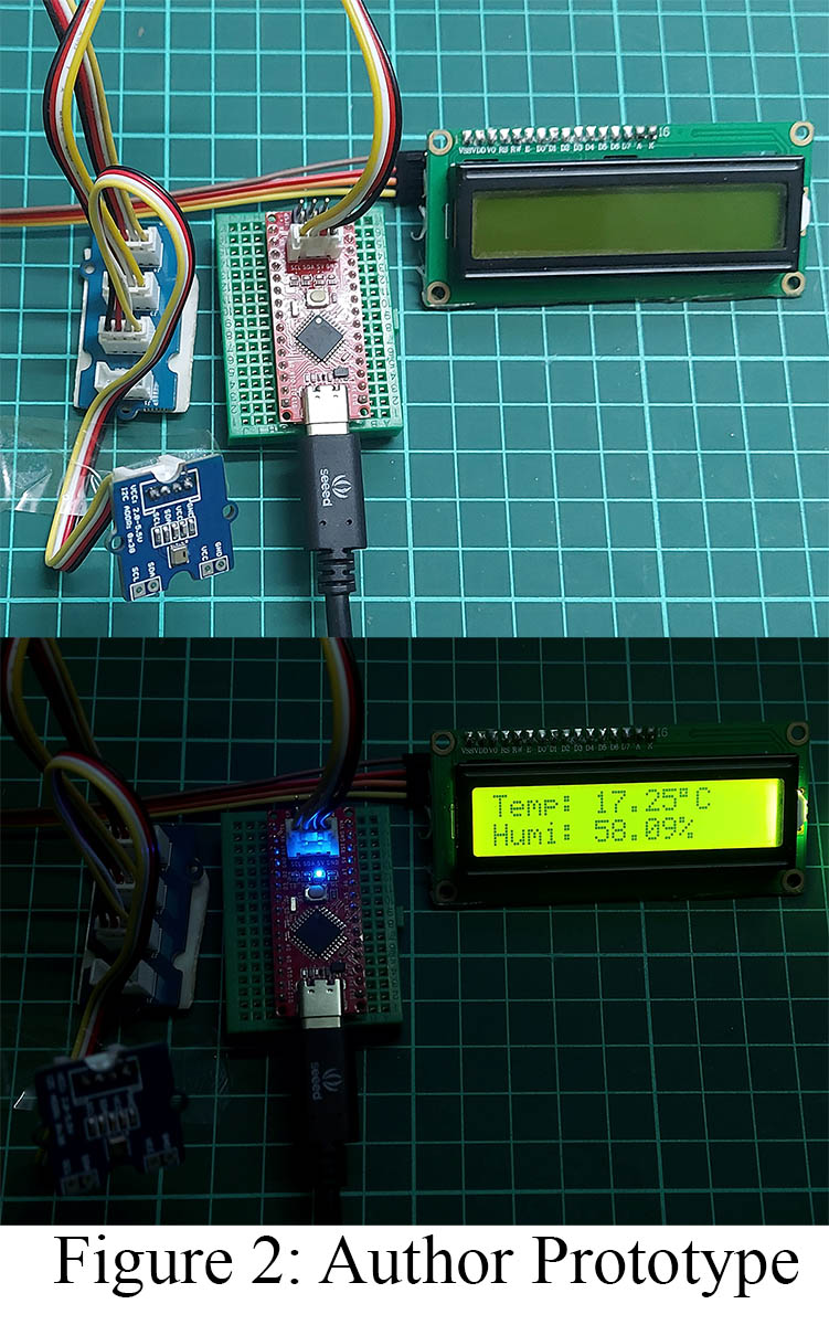
- Processing Unit: Since the sensor unit provides data in standard digital I2C format, the processing unit can directly read the data and process it into the required data format to send it to the Display unit. This unit consists of Arduino UNO or Arduino NANO or its derivatives. Here in this article, we are using Seeeduino nano instead of Arduino nano. Both boards share the same pin configuration and controller but Seeeduino nano has an I2C grove.
- Display Unit: This unit displays data obtained from the Arduino into a 16×2 I2C Alphanumeric LCD.
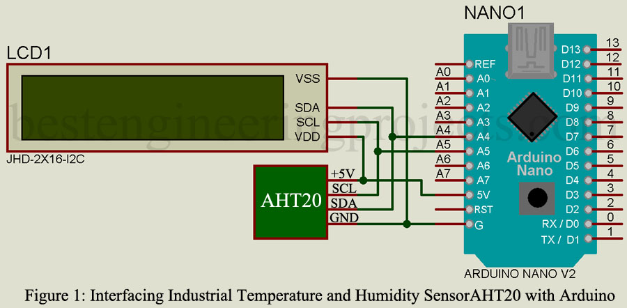
Circuit Description of Interfacing AHT20 with Arduino
SDA(Serial Data) and SCL(Serial Clock) pins of AHT20 are connected to Arduino SDA pins (A4 pin) and SCL pin (A5 pin). These pins are also connected to the SDA and SCL pins of 16×2 I2C LCD. 5V and GND pins from Arduino are connected to VDD/5V and VSS/GND pins of AHT20 and LCD respectively as shown in the circuit diagram.
Here to avoid a messy wiring system and also to connect multiple I2C devices, we can use an IC2 connection Hub. Each I2C device is recognized by its address to avoid conflict. AHT20 has an address of 0×38 which is the same for all AHT20 but the address of a 16×2 I2C LCD can be changed by using pins A0 A1 A2. Instead of using a traditional 16×2 LCD, we are using a 16×2 I2C LCD simply because data communication is possible only with 2 pins (SDA and SCL) which help to simplify the circuit and avoid a messy wiring system.
If you want to interface a traditional 16×2 LCD then its full details can be found on this video link
Software code
|
1 2 3 4 5 6 7 8 9 10 11 12 13 14 15 16 17 18 19 20 21 22 23 24 25 26 27 28 29 30 31 32 33 34 35 36 37 38 39 40 41 42 43 44 45 46 47 48 49 50 51 52 53 54 |
#include <Wire.h> //I2C Wire library #include <ATH20.h> // ATH20 Library #include <LiquidCrystal_I2C.h> //I2C Library LiquidCrystal_I2C lcd(0x27,16,2); // Decrearation of address no. of row and column of I2C LCD ATH20 ATH; void setup() { Serial.begin(9600); lcd.init(); // initialize the lcd lcd.backlight(); lcd.setCursor(0,0); lcd.print("ATH20 Interface"); lcd.setCursor(2,1); lcd.print("with Arduino"); ATH.begin(); delay(2000); } void loop() { lcd.clear(); float humi, temp; int ret = ATH.getSensor(&humi, &temp); if(ret) // GET DATA OK { lcd.setCursor(0,0); lcd.print("Temp:"); lcd.setCursor(6,0); lcd.print(temp); lcd.print((char)223); lcd.print("C"); lcd.setCursor(0,1); lcd.print("Humi:"); lcd.setCursor(6,1); lcd.print(humi*100); lcd.print("%"); Serial.print("humidity: "); Serial.print(humi*100); Serial.print("%\t temerature: "); Serial.println(temp); } else // GET DATA FAIL { lcd.clear(); lcd.setCursor(0,0); lcd.print("ATH20 Fail"); Serial.println("GET DATA FROM ATH20 FAIL"); } delay(1000); } |