In this article you will learn about Cycle redundancy checker, its key parameters, application and special remarks.
Cycle Redundancy Checker | Description
This IC performs error detection by means of a fairly sophisticated method – the cyclic encoding and decoding schemes which are based on the manipulation of polynomials in modulo arithmetic. During the encoding process, the data stream is divided by a selected polynomial, and this division results in a remainder which is attached to the message as check bits. To detect errors, the bit stream containing both data and check bits is divided again by the same selected polynomial. If there are no detectable errors, this division should result in a zero remainder.
In usual computer and communications practice, a standard set of polynomials is most widely used. One of these is based on a series starting with X16, another is used on a similar sixteenth power series with a reverse notation, a third one is based on a X12, and a fourth one is based on X8. For international data transmission, there are CCITT codes, generally based on X16.
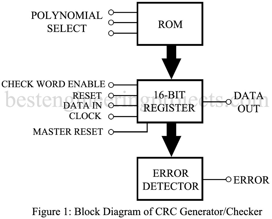
The polynomials themselves are stored in a read-only memory (ROM) as illustrated in figure 1. Three control lines are capable of selecting any one of eight different polynomials stored in the ROM and presenting the 16-bit register with that polynomial code. The data to be encoded or checked is clocked into the 16-bit register and, depending on the function and whether or not a remained occurs, the error detector indicates that an error has been found.
Among the controls for the 16-bit register is an enable signal to allow a check word to be entered from the ROM, a reset signal, and a master reset signal.
Key Parameters of Cycle Redundancy Checker
The electrical characteristics of this IC are essentially the same as those of the TTL digital IC family.
Applications
This is IC used in data communications systems and terminals and in digital computers. It is particularly useful in large memory systems. Digital disk storage system are locations where the CRC generator/checker will be found. The cyclic redundancy method of error detection is also used in some military and space communications systems.
Representative Part Number: Signetics N9401
Comments
This method of error detection requires additional data bits at the end of the actual message train to carry along the reminder which is the result of the polynomial division. The size of the remainder which is the result of the polynomial division. The size of the remainder and therefore the number of bits to be added to the actual message, depends on the polynomial selected and on the nature of the data. Some understanding of digital communications theory is required for the optimum design with this IC.