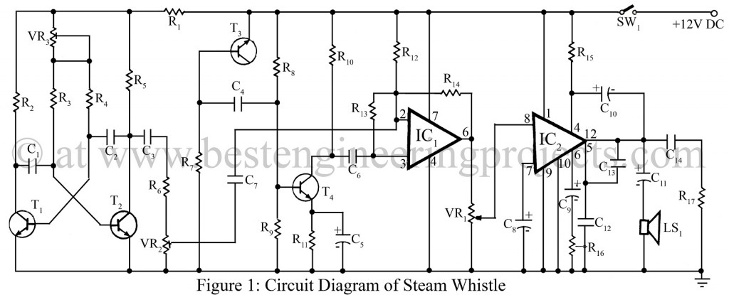
The project “Steam Whistle Circuit using 741 IC” produces a sound similar to that of a steam locomotive whistle. Here, in the circuit Transistor T1 and T2 from a multivibrator, the frequency of which is set by preset VR3. This is the ‘toot’ part of the whistle. Transistor T4 amplifies white noise generated across the reverse-biased transistor T3. White noise and toot mixed by IC1.
The ratio of these is set by preset VR2. IC1 is the most popular and low-cost IC 741 and is used as a low-frequency multivibrator, the output from IC1 is fed to a simple amplifier based around TBA810 IC, IC2.
The positive 12V could be fed to the circuit by a push switch near the controller or by the model train itself using a reed micro switch.
PARTS LIST OF STEAM WHISTLE CIRCUIT USING 741 IC
|
Resistors (all ¼-watt, ± 5% Carbon) |
|
R1 = 47 KΩ, 0.5W R2, R5 = 20 KΩ R3, R4 = 15 KΩ R6 = 4.7 KΩ R7, R9, R10 = 10 KΩ R8 = 150 KΩ R11 = 1 KΩ R12, R13 = 100 KΩ R14 = 220 KΩ R15, R16 = 100 Ω R17 = 1 Ω VR1 = 500 KΩ VR2 = 10 KΩ VR3 = 47 KΩ |
|
Capacitors |
|
C1, C2, C7 = 0.02 µF (Ceramic Disc) C3, C6, C14 = 0.1 µF (Ceramic Disc) C4 = 0.04 µF (Ceramic Disc) C5 = 10 µF, 16V (Electrolytic Capacitor) C8, C9, C10 = 100 µF, 16V (Electrolytic Capacitor) C11 = 470 µF, 16V (Electrolytic Capacitor) C12 = 0.0047 µF (Ceramic Disc) C13 = 0.0015 µF (Ceramic Disc) |
|
Semiconductors |
|
IC1 = 741 (General purpose Op-amplifier) IC2 = TBA810 (Audio Amplifier IC) T1 – T4 = BC108 (Silicon NPN Transistor) |
|
Miscellaneous |
|
SW1 = On/Off switch LS1 = 8Ω/4Ω speaker |
Check out other interesting alarm circuits posted on bestengineeringprojects.com
- Electronic Siren Circuit
- 12 Tones Door Bell
- Rain Sound Generator Circuit
- Simple Warning Alarm Circuit
- Beeper Circuit | 555 Timer Project