Output frequency or tone of the project temperature controlled oscillator circuit varies with the temperature at which the input germanium diode is held. Reverse resistance of D1 varies from 500-Ω to 10 KΩ, when temperature varies between 200C and 800C. (At higher temperature germanium devices show very low resistance.)
This variation of resistance changes the tone of the output sound of the oscillator which is built around the AF amplifier IC (IC1). Instead of germanium diode, base-emitter junction of an ordinary medium-power transistor such as AC128, AC188, 2N360 or 2N610 can be used. The circuit temperature controlled oscillator will not work with silicon diodes.
The circuit temperature controlled oscillator can be made light-controlled by just replacing the diode with an LDR or a reverse biased photodiode.
Circuit Diagram of Temperature controlled Oscillator:
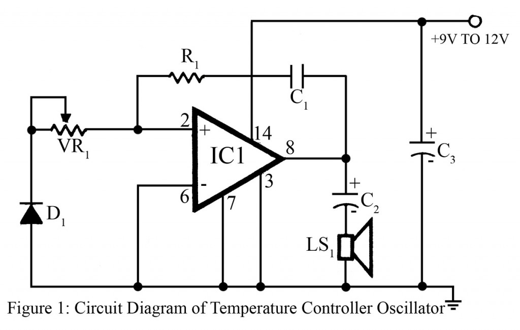
A 9V to 12V ordinary unregulated power supply can be used for this circuit.
Other Oscillator Circuit posted in bestengineeringprojects.com
- A Variable Audio Frequency Oscillator Using Op-amp 741
- Sinewave Feedback L-C Oscillators
- Audio Oscillators
PARTS LIST OF TEMPERATURE CONTROLLED OSCILLATOR CIRCUIT
|
Resistors (all ¼-watt, ± 5% Carbon) |
|
R1 = 56 KΩ VR1 = 10 KΩ |
|
Capacitors |
|
C1 = 0.005 µF (Ceramic Disc) C2, C3 = 220 µF, 16V (Electrolytic Capacitor) |
|
Semiconductors |
|
IC1 = LM380 (Audio Power Amplifier) D1 = DR25 (germanium only) |
|
Miscellaneous |
|
LS1 = 8Ω/ 3Watts |