Popular sinewave feedback L-C tuned oscillators are listed below. These are principally used for generating RF oscillations.
- Tuned Collector Oscillator
- Tuned Based Oscillator
- Hartley Oscillation
- Colpitts Oscillator
- Clapp Oscillator
- Crystal Oscillator
Tuned Collector Oscillator
Figure 1 gives the basic circuit. A parallel tuned L-C circuit placed in the collector circuit constitutes the load impedance and determines the frequency of oscillation. The output voltage developed across the tuned circuit is inductively coupled to the basic circuit through the coil L2. The winding direction of the two coils L1 and L2 are so chosen that positive feedback takes place from the collector circuit to the base circuit. The dots are placed on coils L1 and L2. When the dotted end of L1 is positive, the dotted end of L3 also become positive.
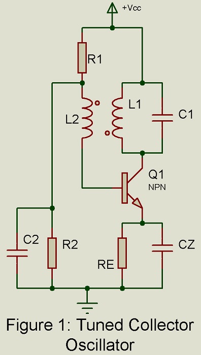
The tuned circuit in the collector circuit resonates at frequency  . At this frequency, the impedance of the tuned circuit is purely resistive and large. The ac voltage drop across the inductor L1 from collector to ground is 1800 out of phase with the voltage from base to ground. The transformer winding directions are so chosen as to produce a phase shift of another 1800 assuming the secondary to be unloaded. Then the total loop phase shift is exactly 3600 or 00 and oscillations are produced at the frequency of resonance
  . However, the secondary is always loaded to some extent. Hence the frequency of oscillation i.e. the frequency at which Barkhausen criterion is satisfied differs from the frequency of resonance of the tuned circuit.
Analysis using small signal equivalent circuit for the transistor and the Barkhausen criterion  yields the following results:
- Condition for sustained oscillations:
 …………………..(1)
Where M is the mutual inductance between coils L1 and L2 and R is the load resistance of the secondary coil L2 reflected to the primary coil L1.
Resistances of the coils L1 and L2 have been neglected.
- Frequency of oscillation:
 ……………..(2)
Where is the frequency of resonance of L1 and L2 and equals  .
.
From Eq. (2), we conclude that in tuned collector oscillator, the frequency of oscillation  exceeds the frequency of resonance of the tuned circuit.
Tuned Based Oscillator
Figure 2 gives the basic circuit. A parallel tuned L-C circuit placed in the base-to-ground circuit determines the frequency of oscillation. The output developed across the tuned circuit is inductively coupled to the collector circuit through the coil L2. The winding direction of the coils L1 and L2 are so selected that positive feedback takes place from the collector circuit to the base circuit resulting in oscillations. The tuned circuit in the base circuit resonates at frequency . At this frequency, the impedance of the tuned circuit is purely resistive and large.
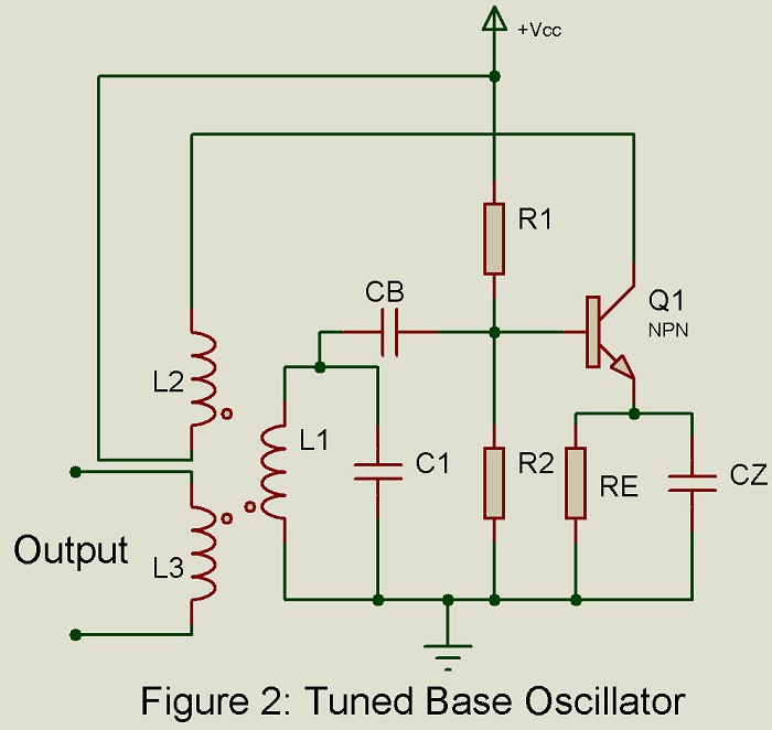 The voltage drop across the inductor L2 is 1800 out of phase with the base to ground voltage. The transformer winding direction are so chosen as to produce phase shift of another 1800 assuming the oscillator to be non-loaded. Then the total phase shift is exactly 3600 or zero degree. However, the secondary is always loaded to some extent. Hence the frequency of oscillation differs slightly from the frequency of resonance of the tuned circuit.
Hartley Oscillator
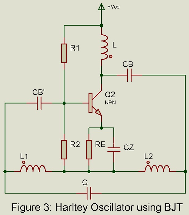
Figure 3 gives thew circuit of Hartley oscillator using BJT. The collector supply voltage Vcc is applied to the collector through inductor L whose reactance is high compared with that of L2 and may, therefore, be neglected. Capacitor Cb has a low reactance at the frequency of oscillation and may also be neglected in the equivalent circuit. At dc i.e. zero frequency, Cb, therefore, prevents collector supply Vcc from getting short circuited by L in series with L2. The parallel combination of Re and Cz in conjunction with= R1 – R2 combination provides stabilized self-bias. The circuit operates as class C amplifier with infinity gain. The tuned circuit constituted by L1 – L2 – C determines the frequency of resonance. Since the tuned circuit extends right from the input circuit, the feedback needed for sustained oscillation takes place through the tuned circuit itself.
Result of Analysis: Analysis making use of the equivalent circuit and the Barkhausen criterion yields the following results:
- Condition for sustained oscillations
 ………(3)
 ………(3)
If there exists mutual inductance M between coils L1 and L2 then the condition for sustained oscillation is,
 …….(4)
- Frequency of oscillation,
 ….(5)
….(5)
Where  and
and  ,
,
 …..(6)
From Eq. (5) we conclude that in Hartley oscillator, the frequency of oscillation is slightly smaller than the frequency of series resonance of L1, L2 and C.
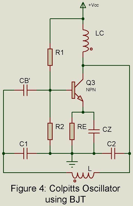
Colpitts Oscillator
Figure 4 gives the basic circuit. The collector supply voltage Vcc is applied to the collector through the inductor Lc whose reactance is high compared with the reactance of capacitor C2. Hence Lc may be omitted from the equivalent circuit. Parallel combination of Rc and Cz along the resistor R1 – R2 provides the stabilized self-bias. The tuned circuit consists of capacitor C1 and C2 and inductor L. It extends from the collector circuit to the base circuit and basically determines the frequency of oscillation. The feedback is through the tank circuit itself.
Result of Analysis: Analysis making use of the small signal h-parameter model and the Barkhausen criterion yields the following results:
- Condition for sustained oscillation …..(7)
- Frequency of oscillation …….(8)
 …..(7)
 …….(8)
Where  and
and  and is the frequency of resonance of C1, C2 and L and is given by
 …(9)
…(9)
From Eq. (8) we conclude that in the case of Colpitts oscillator, the frequency of oscillation is slightly greater than the frequency of series resonance of C1, C2 and L.
Clapp Oscillator
Figure 5 gives the basic circuit of Clapp oscillator. It is modified version of Colpitts oscillator. The main difference between the two circuits lies in the introduction of another capacitance C3 in series with the coil L.
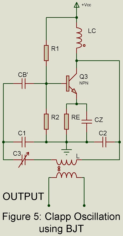
The capacitance C1 is made so large as to reduce the effect of collector capacitance variation due to collector voltage change. The emitter junction capacitance depends on the emitter current. In the circuit of Fig 5, resistor R2 in the biasing network may be in the form of a thermistor so that the emitter current gets reduced at high temperatures.
The frequency of oscillation is given by,
 ……(10)
Capacitors C1 and C2 are kept fixed while capacitor C3 is used for tuning purpose.
Further 
In that case, the frequency of oscillation is approximately given by,
 ……(11)
Thus, the frequency of oscillation is nothing but the frequency of series resonance of L and C3.
This condition for sustained oscillation is,  …..(12)
High frequency stability is obtained by (i) enclosing the entire circuit in a constant temperature chamber and (ii) by maintaining the operating voltage constant with the help of a zener diode.
Crystal Oscillator
Piezo-electric Quartz Crystal
For excellent stability of frequency of oscillation in the RF range, we may use a piezo-electric quartz crystal in place of the L-C tuned circuit in the oscillator. Fig 6 gives the electrical equivalent circuit of a piezo-electric quartz crystal.
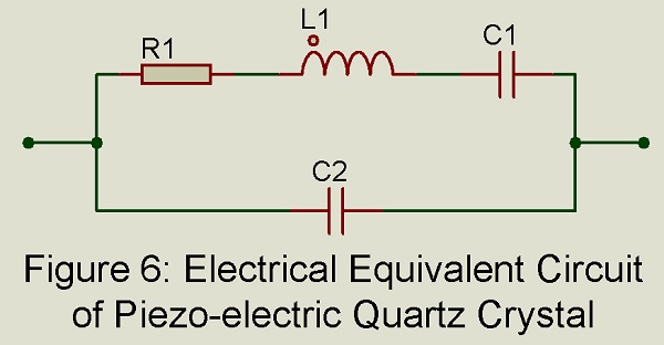
In Fig 6, element R1 L2 C1 from a series resonance circuit resonating at frequency fs. The impedance of this series circuit at resonance is restive and equal to R1. Complete circuit including C2 along with R1 L2 C1 forms a parallel tuned circuit resonating at frequency fp. under parallel resonance condition at fp, the impedance of the complete tuned circuit is again resistive but extremely large. Frequency fp is greater than fs but extremely close to it. When piezo-electric quartz crystal is used in place of conventional L-C tuned circuit in an oscillator, the frequency of oscillation is determined by the value of elements R1 L1 C1 and C2 but this frequency must lie in the frequency range from fs to fp. Since fs and fp are extremely close, an extremely high order of stability of frequency of oscillation is obtainable in a crystal oscillator i.e. an oscillator using quartz crystal.
Crystal Oscillator Circuit
A huge variety of crystal oscillator circuits are possible depending on (i) which active device is used, BJT or FET and (ii) part of the circuit where crystal is placed.
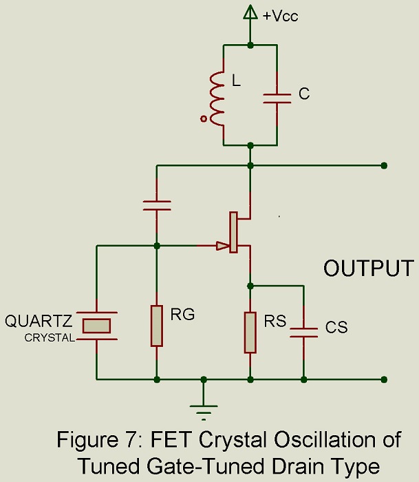
Tuned Gate-Tuned Drain Crystal Oscillator
Figure 1 shows an FET crystal oscillator of tuned gate-tuned drain type. Here drain-to-gate capacitance Cdg forms the feedback path from drain (output) to the gate (input). Stray wiring capacitance Cs also gets added to this circuit. For sustained oscillation, it is necessary that the L-C tuned circuit in the drain circuit and the quartz crystal equivalent crystal equivalent circuit in the gate circuit be inductive. Hence this circuit will oscillate at a frequency which lies between the frequencies fs and fp of the crystal. Hence high stability of frequency of oscillation results.
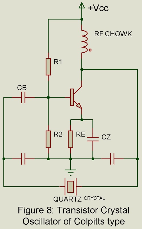
Colpitts Crystal Oscillator using BJT
Figure 2 shows crystal oscillator using Colpitts circuit using BJT. Here crystal is placed in place of inductor L of Colpitts tuned circuit. in this case also, the frequency od oscillation lies in the range determined by frequencies fs and fp of the quartz crystal.