Blown fuse indicator circuit of the kind described here provides an ideal solution in such case. It indicates whether fuse is good or blown by generating audio alarm and glowing LED.
Circuit Description and Working of Blown Fuse Indicator
This circuit is based on 555 timer wired as an astable multivibrator. When the fuse is not blown, positive voltage is applied at junction P (IC’s pins 2 and 6) through R2 and D1. This holds the voltage at the junction above 2/3 Vcc and prevents the IC from oscillating.
When the fuse blown off, IC is free and starts oscillating. Pin 3 drives the loudspeaker (8-ohm) and gives an audio alarm. D2 lights with a constant intensity when the fuse is not blown but dims when it is blown off.
This circuit can be connected with the power supply unit in your home or office.
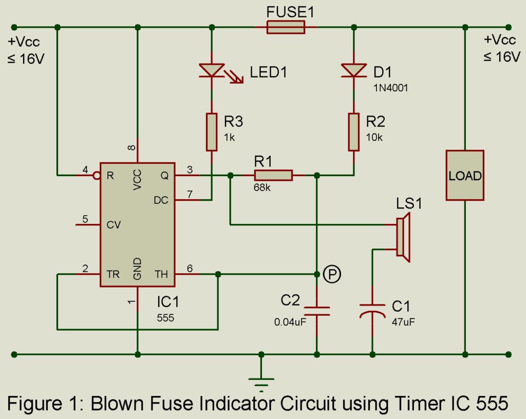
If you wish to use this circuit with a low power supply (say about 5V), then it is better to reduce the value of R3 to about 330 ohms. (In any case, the current through LED should be less than 20 mA). Frequency of oscillation may be changed by changing C2’s value to 0.001uF or 0.01uF, or even 0.02uF.
If you wish to change the frequency by changing R1, then make sure that R1 and R2 are such that at point P, the voltage is above 2/3 Vcc. Voltage across R1 (assuming voltage at pin 3 corresponding to low state is oV) is given by

Where Vcc is the supply voltage, VTD the threshold voltage of the diode (D1), and VTD = 0.6V. It should be > 2/3 Vcc. For 555 IC, Vcc is such that 5V ≤ Vcc ≤ 16V.
PCB Diagram:
PCB diagram of Blown fuse indicator is designed using proteus 8.1 design suite. Actual side solder side and component side is shown below. Download the PCB in PDF form from the link below.
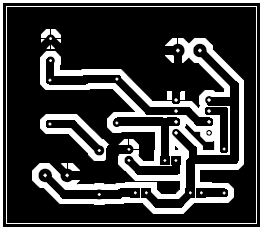
Figure 2: Solder Side PCB of Blown Fuse Indicator circuit
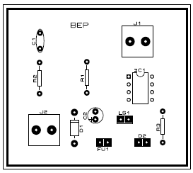
Figure 3: Component Side PCB of Blown Fuse Indicator circuit
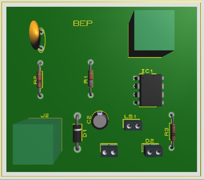
Figure 4: 3D view of Blown Fuse Indicator circuit
Click here to download the PCB diagram
Check out other Fuse related circuit posted in bestengineeringprojects.com
- Electronic Fuse Using Op-amp 741
- Electronics Fuse Circuit | Electronic Circuit Breaker
- High Current Regulator Circuit
- Load Protector Circuit and Remote Switching
PARTS LIST OF BLOWN FUSE INDICATOR CIRCUIT
| Resistors (all ¼-watt, ± 5% Carbon else Specified) |
| R1 = 68 KΩ
R2 = 10 KΩ R3 = 1 KΩ |
| Capacitors |
| C1 = 47 µF, 25V (Electrolytic Capacitor)
C2 = 0.04 µF (Ceramic Disc) |
| Semiconductors |
| IC1 = NE555 (Timer IC)
D1 = 1N4001 (Rectifier Diode) LED1 = 5mm, any color LED |
| Miscellaneous |
| LS1 = 8Ω Loudspeaker
FUSE LOAD |