RC oscillators are principally used for generating audio frequencies. Two popularly used RC oscillators are (i) RC phase shift oscillator using either BJT or FET and (ii) Wien Bridge oscillator. Another popularly used audio oscillator is the Beat Frequency Oscillator (BFO). We here consider these three audio oscillators.
RC Phase Shift Oscillator using BJT.
Figure 1 gives the basic circuit. It is a sinewave feedback oscillator and uses an amplifier followed by three section R-C phase shift network. Output of the last section is fed to the base. We assume that phase shift network does not load the internal amplifier. Then the internal amplifier causes the amplified output voltage to be 1800 out of phase with the input voltage at the base. The three-section phase-shift network produces additional phase shift which is a function of frequency and equals 1800 at some frequency, each section producing a phase shift of 600. At this frequency, the total phase shift from base through the basic amplifier, phase shift network and back to the base exactly equals 3600 or zero degree. Then this frequency forms the frequency of oscillation i.e. the frequency at which the circuit produces oscillations provided that the gain of the basic amplifier is large enough.
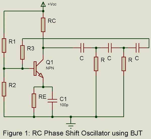
Phase shift oscillator of figure 1 uses a BJT as the internal amplifier. Voltage shunt feedback is used i.e. feedback voltage is proportional to the output voltage and the feedback voltage is fed in shunt with the voltage at the input i.e. at the base B.
Result of Analysis: Analysis of the circuit may be done by (i) replacing the BJT by its approximate h-parameter model (provided  ) (ii) applying KVL to the circuit and (iii) making us of Barkhausen Criterion. Analysis yields the following results:
- Frequency of oscillation:
 …….(1)
 …….(1)
Where 
- For sustained oscillations: Following inequality must be satisfied:
 …….(2)
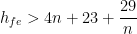
From inequality (2), value of n which gives the minimum hfe comes out to be 2.7. For this optimum value of  , we get hfe = 44.5. hence a phase shift oscillator must be use BJT having hfe > 44.5.
Applications: RC phase shift oscillator is well suited for use as an audio oscillator for generating frequencies in the range 20 Hz to 200 KHz. This includes audio frequency range i.e. from a few Hz to 20 KHz. Hence RC phase shift oscillator is popularly used as an audio oscillator. For generating different audio frequencies, variable air capacitors are used as circuit elements C in the phase shift network. Such capacitors vary over capacitance range of about 10:1, typically from 40 pF to 450 pF. Hence as per Eq (1), it becomes possible to vary the frequency in the range of 10:1. Typically for one set of resistors R in the phase shift network, frequency range covered may be from 20 Hz to 200 Hz. Similarly, by using other sets of resistors R, frequency range covered may be from 200 Hz to 2 KHz, 2 KHz to 20 KHz and from 20 KHz to 200 KHz. To keep the distortion low, phase shift oscillator is operated in class A condition.
For generating higher frequencies in MHz range, RC phase shift oscillator has no definite advantage over L-C tuned oscillators.
RC Phase Shift Oscillator using FET
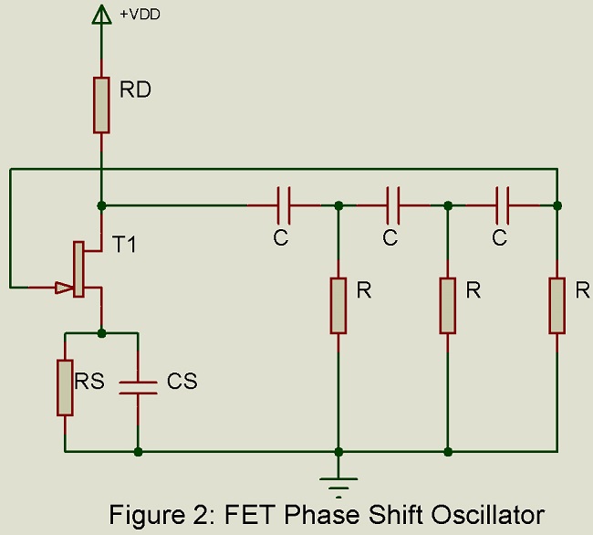
Figure 2 gives the basic circuit. The circuit consists of common source FET amplifier followed by a three section RC phase network. The output of the last section is fed to the gate. We assume that the phase shift network does not load the internal amplifier. Then the internal amplifier causes the amplified output voltage V0 to be 1800 out of phase with the input voltage at the gate. The three-section phase shift network produces additional phase shift which is a function of frequency and equals 1800 at some frequency of operation.
At this frequency, the total phase shift from the gate through the internal amplifier and phase shift network and back to the gate is exactly 3600 or zero degree. Then this frequency forms the frequency of oscillation i.e. the frequency at which the circuit produces oscillations provided that the gain of the internal amplifier is large enough.
FET phase shift oscillator uses an FET amplifier and voltage series feedback i.e. feedback voltage is proportional to the output voltage and is fed in series with the input signal at the gate.
Result of Analysis: Analysis of the circuit may be done by (i) replacing the FET by its small signal equivalent circuit (ii) applying KVL to the circuit and (iii) making use of Barkhausen Criterion.
Analysis Yields:
- Frequency of oscillation: …..(3)
- Feedback ratio:
 …..(3)
For sustained oscillations, | | must not be less than unity. Hence |A| i.e. the magnitude of the voltage gain of the internal amplifier must be at least 29. Hence we must use FET with
  .
.
FET phase shift oscillator is also used to generate signal over a wide range of frequencies. Thus using one set of resistors with 3 capacitors ganged together to vary over a capacitance range in the ratio 1:10, the frequency may be varied over the range from say 20 Hz to 200 Hz. Similarly using other sets of resistors, we may select frequency ranges of 200 Hz to 2 kHZ, 2 KHz to 20 KHz and from 20 KHz to 200 KHz.
Wien Bridge Oscillator
This oscillator is also popularly used for generating audio frequencies. The Wien bridge oscillator has the advantage over the phase shift oscillator in that the generated frequency may be varied over a range of 1:10 by varying only one capacitor.
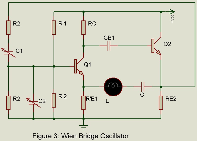
Figure 3 gives the basic circuit. The internal amplifier consists of two stages. The first stage uses transistor Q1 as a CE amplifier, while the second stage uses transistor Q2 as a CC amplifier. The output of the second stage is fed back to the input of the first stage through the feedback network consisting of R1 C1 and R2 C2 combinations, providing negative feedback. Simultaneously, positive feedback is provided from the emitter of the second transistor Q2 to the emitter of the first transistor Q1. R1 C1 and R2 C2 elements of the bridge circuit provide negative feedback, which prevents oscillations at all frequencies except the null frequency of the bridge. Lamp L limits the amplitude of oscillations. An increase in the resistance of the lamp with an increase in the amplitude of oscillations reduces the positive feedback, which, in turn, reduces the amplitude of oscillations.
Beat Frequency Oscillator (BFO)
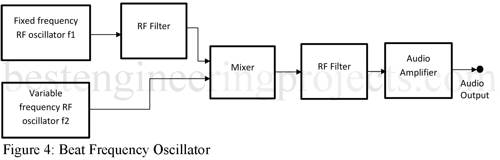
Figure 4 gives the block diagram of BFO. In this circuit arrangement, outputs of two RF oscillators of slightly different frequencies f1 and f2 are applied simultaneously to a heterodyning or mixer device. At the output of the mixer, we get the sum and difference terms of frequencies mf1 +/- nf2 where m and n are integers. The difference frequency (f1 – f2) is so arranged that it lies in the audio frequency range. An RF filter removes all RF components, leaving only the audio frequency difference term (f1 – f2), which is then applied. The BFO is an extremely popular audio frequency generator since the entire audio frequency range extending from 20 KHz or higher down to as low as 1 Hz may be occurred with the movement of a signal dial. Thus, if frequency f1 is fixed at 400 KHz and f2 is variable from 380 KHz to 400 KHz, the audio frequency voltage available at the output will have its frequency variable from 20 KHz to 1 Hz.
Hi there.
Thanks for the oscillator projects. Please note Figure 4, referring to Beat Frequency Oscillator (BFO),
Is missing.
Best,
Andre
Hi Andre,
Thank you for reaching out and for your keen observation. I’ve updated the article and added Figure 4 for the Beat Frequency Oscillator (BFO). You can now view the corrected version.
Please let me know if there’s anything else I can assist with.
Best regards,