The world is all about visualization. Mesmerizing illumination has been introduced which provides a different level of satisfaction for human eyes. Using multi-pattern LEDs lights in a cubical representation is our contribution to this global trend. The project; LED Cube 4x4x4 Circuit using AT89c2051 microcontroller to create several light patterns. The cube designed for specific use in science laboratories is much easier to assemble. Previously, we had posted an LED Matrix Display using Arduino.
Circuit Description of LED Cube 4x4x4 Circuit using AT89C2051
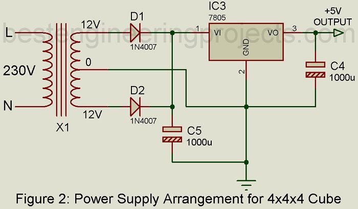
You can see the entire circuit of the project; “LED Cube 4x4x4 Circuit using AT89C2051” is demonstrated in fig.1. The project is fabricated around the AT89C2051 microcontroller (IC2) as its heart component and is surrounded by supporting blocks of a 4-to-16 decoder 74HC154 (IC3), four BC547 transistors (T1 through T4), and some other discrete components. To build the power supply for this specific design, a separate module is required shown in figure 2. A step-down transformer (X1) along with two 1N4007 rectifier diodes (D1 and D2) and a 5V regulator 7805 (IC3) are included in the design of the power circuit.
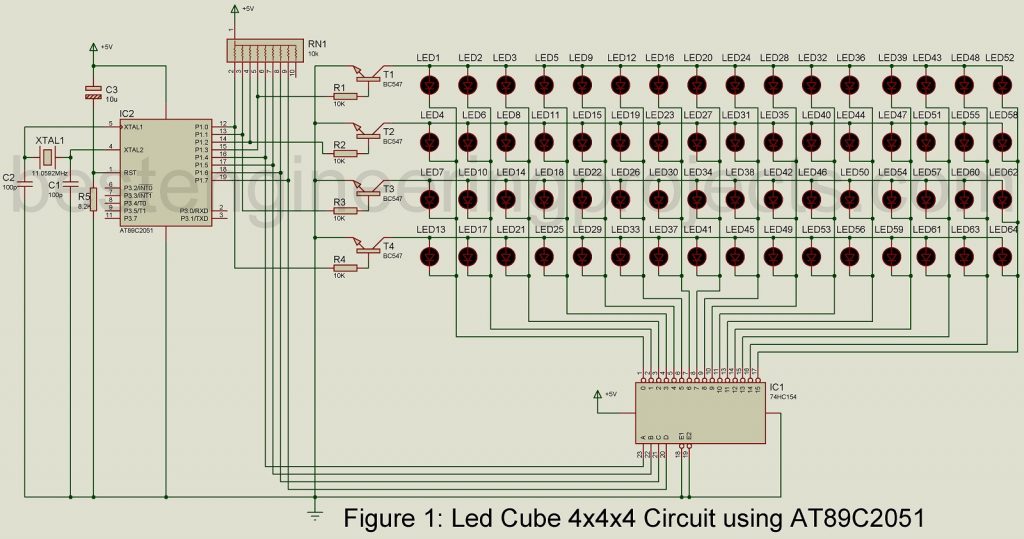
To construct the cubical structure, we use 64 different LEDs. All these LEDs are arranged in a 4 rows x 16 column arrangement. The connection between the LEDs, 74HC154 decoder, and AT89C2051 microcontroller is established. The microcontroller used in the project belongs to the MCS-51 family controller and has 20 pins in total out of which there are only two input/output ports.
To create the variation of lighting effects, four transistors (T1-T4) are employed. And, these transistors are connected to the microcontroller through port pins P1.3 through P1.0 respectively. Similarly, port pins P1.4-P1.7 are assigned to control the decoder IC3.
Before setting up the project, test the 64 LEDs to avoid failure at the end, and to do so, either connect LEDs to a multimeter set in a diode mode or use a button cell battery.
Cube construction | LED Cube 4x4x4 Circuit using AT89C2051
The construction of an LED cube is much easier than it looks. Start the construction from the top layer, it will make the work easy. Take the help of a template, cardboard, and make holes. The distance between each hole must be around 25.4mm. This template supports the LEDs’ structure and aids the soldering process as well.
Now, fit the 16 LEDs in the holes of the cardboard and with the help of needle-nose pillars or something similar, bend the cathode/negative terminals of each LED in the board at an angle of 90º, note that cathode is the shorter terminals of the LED. Now, with a proper soldering seal, all the negative terminals of the LED are in the first layer. Follow, soldering process with remaining positive terminals of the LEDs from the first layer to the LEDs of the second layer. Repeat the layers following the same pattern and solder the anode terminal of the fourth layer LEDs.
Hence, the cubical structure will be ready
Software for LED Cube 4x4x4 Circuit using AT89C2051
The microcontroller is loaded with the program to create visual effects, this program is written in C, Keil µvision 4 IDE is used as a compiler. The program can be modified to change the effects as required. In this particular program, there are five loop structures(stage1-stage-5) that illustrate the control mechanism of the LED Cube 4x4x4 project. As mentioned above, you are free to make necessary changes and loop structures to achieve a new effect. The controller is fed with the hex code developed by the compiler and the project works smoothly.
CLICK HERE TO DOWNLOAD SOFTWARE CODE
PARTS LIST OF LED CUBE 4X4X4 CIRCUIT USING AT89C2051
| Resistors (all ¼-watt, ± 5% Carbon) |
| R1 – R4 = 10 KΩ
R5 = 8.2 KΩ RN1 = 10 KΩ Resistor Network |
| Capacitors |
| C1, C2 = 33pF (Ceramic Disk)
C3 = 10 µF, 16V (Electrolytic Capacitor) C4 = 1000 µF, 16V (Electrolytic Capacitor) C5 = 1000 µF, 35V (Electrolytic Capacitor) |
| Semiconductors |
| IC1 = 74HC154 (Decoder IC)
IC2 = AT89C2051 (Microcontroller) IC3 = 7805 (5V Series Regulator) T1 – T4 = BC547 (NPN Transistor) D1, D2 = 1N4007 (Rectifier Diode) LED1 – LED4 = 5mm any color LED |
| Miscellaneous |
| X1 = 230V AC Primary to 12V-0-12V, 500mA Secondary Transformer
XTAL1 = 11.0592MHz Crystal Oscillator Heat-sink for IC3 IC Sockets |