Direct Digital Synthesis
Direct digital synthesis (DDS) systems became economically feasible in the late 1980s. They offer some advantages over analog synthesizers but generally tend to be somewhat more complex and expensive. They are, however, useful for some applications as will be discussed. The digital logic used can improve on the repeatability and drift problems of analog units that often require select-by-test components. These advantages also apply to digital filters that have replaced some standard analog ones in recent years. The disadvantages of DDS (and digital filters) are the relatively limited maximum output frequency and greater complexity/cost considerations.
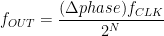
A block diagram for a basic DDS system is provided in Fig. 1. The numerically controlled oscillator (NCO) contains the phase accumulator and read-only memory (ROM) look-up table. The NCO provides the updated information to the digital-to-analog converter (DAC) to generate the RF output.
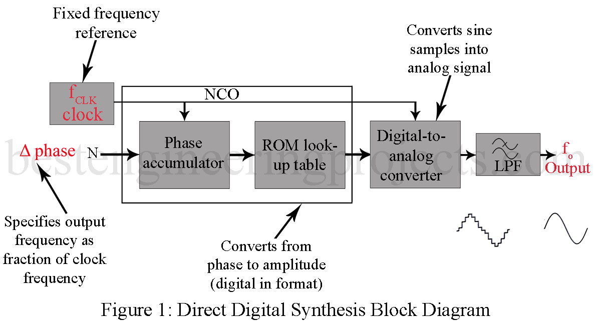
The phase accumulator generates a phase increment of the output waveform based upon its input ( phase in Fig. 1). The input ( phase) is a digital word that, in conjunction with the reference oscillator (fCLK), determines the frequency of the output waveform. The output of the phase accumulator serves as a variable-frequency oscillator generating a digital ramp. The frequency of the signal is defined by phase as
 …(1)
…(1)
for a N-bit phase accumulator.
Translating phase information from the phase accumulator into amplitude data is accomplished by means of the look-up table stored in memory. Its digital output (amplitude data) is converted into an analog signal by the DAC. The low-pass filter provides a spectrally pure sine-wave output.
The final output frequency is typically limited to about 40% of fCLK. The phase accumulator size is chosen based upon the desired frequency resolution, which is equal to (fCLK/2N) for a N-bit accumulator. The Analog Devices AD9955 can operate with clock frequencies as high as 100 MHz. It contains a 32-bit phase accumulator and a 15-bit phase to 12-bit sine amplitude converter. Recall that the phase-to-amplitude transformation is performed by the read-only memory look-up table.
Example 1: Calculate the maximum output frequency and frequency resolution for the AD9955 DDS when operated at fCLK MAX.
Solution:
The maximum output frequency is approximately 40% of fCLK MAX
= 0.40 x 100 MHz
= 40 MHz
The frequency resolution is given by (fCLK/2N) = 100 MHz / 232 = 0.023 Hz
Advantage of Direct Digital Synthesis
The preceding example shows that DDS offers the possibility for extremely small frequency increments. This is one of the advantages offered by DDS over analog synthesizers. Another DDS advantage is the ability to shift frequencies very quickly. This characteristic is very useful for the spread-spectrum systems.
The disadvantage of Direct Digital Synthesis
The disadvantages of DDS include the limit on maximum output frequency and higher phase noise. Spurious changes in the phase of the synthesizer’s output result in energy at frequencies other than the desired one. This phase noise is often specified for all types of oscillators and synthesizers. It is usually specified in  at a particular offset from center frequency. A specification of
  at a 10-kHz offset means that noise energy at a 1-Hz bandwidth 10 kHz away from the center frequency should be 90 dB lower than the center frequency output. In a sensitive receiver, phase noise will mask out a weak signal that would otherwise be detected.