In this article, you will learn to design DIY Solar 18650 Charger as well as a solar emergency light. This device will help you charge a device through a USB port and it has an inbuilt led in it, which will serve as an emergency light when needed.
Introduction of DIY Solar 18650 Charger with Emergency Light:
Solar energy is the best way to reduce your energy consumption as it uses sunlight to produce energy. Sunlight can be utilized neatly, without harming our environment. So, here we are also going to utilize solar energy to charge Li-ion batteries. Using this device one can charge a mobile phone through a dedicated USB and/or uses it as an emergency light. Previously, we had posted a circuit of a Lithium-ion battery charger using LM317.
Components required
- 6V, 150mA Solar panel x 1
- TP4056 Li-Ion Battery charger module x 1
- DC 1V~5V input to 5V Output boost module with USB x 1
- 18650 battery or any other Li-ion battery x 1
- battery holder in case of 18650 battery
- 1N4007 Rectifier diode x 1
- LED Array x 1
- ON/OFF Switch x 2
- Box
Description of DIY Solar 18650 Charger with Emergency Light
The circuit diagram is shown in figure 1 and is designed using commonly available components. The arrangement is very easy and understandable.
Figure 1: DIY Solar 18650 Charger with Emergency Light
Figure 2: DIY Solar Li-Ion Charger with Emergency Light
Solar Panel Connection:
The mini solar panel used in this project is a small 6V panel with a small output current of 150 mA. Also, this output of 6V might fluctuate between 5V to 7.5 V depending on the intensity of light. This panel has two terminals marked as “+” and “-” or have two wires of different colors. Here the panel we are using has white for “+” and black for “-”, in your case it might be different. So before connecting make sure the polarity of this wire. In any confusion about this wire use a multimeter.
How to identify the polarity of the wire of the solar panel?
- Take a multimeter and adjust it to measure the 20V voltage range.
- Connect the multimeter “COM” probe to one wire from the panel and the “V” probe to another wire from the panel.
- Go in sunlight and measure the voltage of the panel and it will display any voltage between 5V and 7.5V.
- If the polarity of voltage displayed on the multimeter is of negative quantity then the polarity of the wire is reversed else the wire connected to the “COM” probe is “-” and the “V” probe is “+”.
After finding the polarity of the panel wire, now it’s time to connect the diode.
Purpose and connection of Diode
At night time or say in the dark the potential difference (voltage) of solar is less than the battery (potential) voltage. The direction of voltage is always towards lower potential from higher potential i.e. in dark (night) the voltage starts to flow towards the solar panel from the battery. In order to solve this issue, a diode is used here. The diode 1N4007 is a general-purpose rectifier diode and you can use other alternatives too like 1N4001 and/or another rectifier diode. The main purpose of this diode is to block the reverse flow of voltage i.e. it blocks the flow of voltage from the battery back to the solar panel. This diode also acts as a reverse polarity protector i.e. it protects the device from the reverse connection of the solar panel. The positive terminal of the solar panel is connected to the cathode of the diode (1N4007), where the anode is connected to the IN+ terminal of the TP4056 battery charger.
TP4056 Li-ion Battery Charger Module
This module can charge the battery in two-mode i.e. constant current and constant voltage with max. charge voltage of 4.2V with 1.5% accuracy. The module also protects the battery from overcharge, deep discharge, and overcurrent.
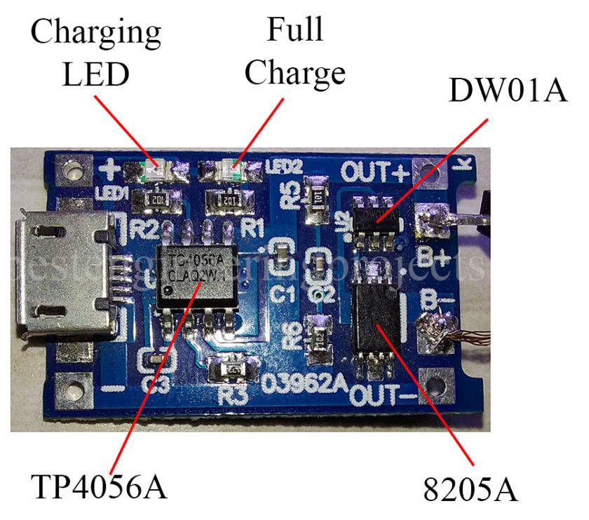
Figure 3: TP4056 Battery Charging Module
TP4056 Li-ion battery charger module has three main ICs with dedicated charging and a full charger indicating LEDs. The three ICs are:
- TP4056 is a linear charger IC for single-cell lithium-ion battery. It has two modes of charging i.e. constant current and constant voltage. This IC can be programmed for a constant charge current from 130mA to 1000mA (1A) by using a resistor of the corresponding value. The module is programmed for a 1000mA constant charging current.
- DW01 is a battery protection IC that protects the battery from overcharge, deep discharge, and overcurrent. This IC sense the voltage of a li-ion battery and switches the MOSFET for the load. The overcharge detection voltage is
whereas overcharge release voltage is
. The deep discharge detects voltage is
and overcurrent detection voltage is
.
- 8205A is a dual N-channel MOSFET and is used to switch the load. The small package can deliver a high current of about 6A. When battery voltage becomes as low as deep discharge voltage then DW01 switch off the MOSFET then no current will be delivered from the battery.
The diode’s anode is connected to the “in+” pin of TP4056 where solar “-” (black) wire is connected directly to the “in-” of the TP4056 module. Here, the input side connection is completed. So, now, let us see the output side. On the output side you can see four connections; namely, “OUT+”, “B+”, “B-”, and “OUT-” respectively as shown in the figure.
Connect the positive terminal and negative terminal of the battery to “B+” and “B-” of TP4056 respectively. The output of the 18650 Li-ion battery is 3.7 V (max 4.2V) but we need 5V to charge devices like mobile phones, or power the MCU through USB. So here we need a boost converter.
Figure 3: Boost Converter with USB
Now, it’s time to connect loads i.e. USB boost module and LEDs array. Here we are using two dedicated switches in order to switch two loads individually i.e. one switch is used for the LEDs array and another switch is used for the USB boost module. The positive terminal of these two loads is connected to “OUT+” where the negative terminal is connected to the “OUT-” of the TP4056 module.
The boost converter used has a 2.6V-5.5V input to 5V output step-up converter. Hence, it can accept the input may be any value between 2.6V to 5.5V but the output produced is constant at 5V. The boost module used here can deliver 5V output @ 2A. You can power your MCU i.e. Arduino, ESP, etc. or you can even charge your mobile in case of emergency.
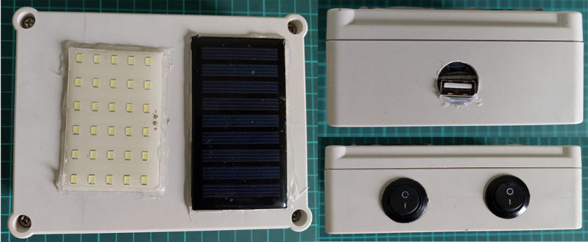
Figure 5: Author Prototype
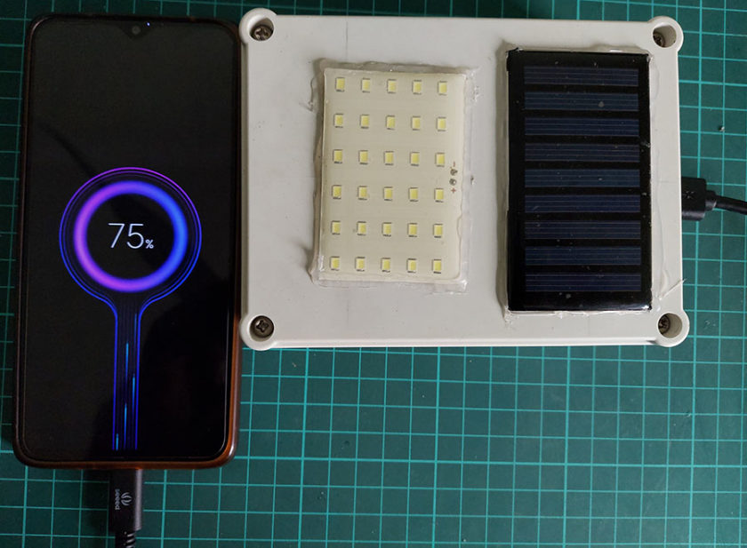
Figure 6: Author prototype when mobile is charging
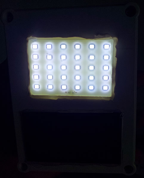
Figure 7: Author Prototype when emergency light is ON
Note: Here in this project a mobile phone Li-ion battery is used but you can use any single-cell Li-ion battery like a 18650 Li-ion battery. We have tested this circuit with different types of Li-ion batteries and the test result is positive.


