Introduction to Offline UPS Circuit
We all know that most electrical and electronic appliances are solely powered by the AC supply and the problem arises when the power is cut off in the middle or there is no power at all. In such cases, uninterrupted supplies are what we look out for. This is one of those uninterrupted power supply circuits. The fact that it provides an instant power supply from the batteries than standby generators that take long to operate, makes it more practical. To make the use of this device easier, the online UPS circuit has batteries directly connected to the inverter which stays in on state, and hence no additional switches are required to turn on the circuit during power failure.
But, this project is based on the concept of an offline UPS. The device is turned on only when the AC mains are cut. These circuits are available readily and can be used as per our requirements. But, it doesn’t mean that we can’t create our customized version of Ups. A sample of an economic offline UPS circuit with 350VA capacity is given below. This is perfect for any equipment that operates below the defined limit. We can surely extend the capacity of the device with slight modifications to the components used.
Description of Offline UPS Circuit
The entire diagram of the offline UPS circuit is divided into 3 main sections as listed below. The circuit is sectored into four main portions; Mains/inverter Change-over Section, Inverter Section, Battery-status-indicator section, and oscillation section.
These portions are shown clearly in the main circuit diagram.
Mains/inverter changeover section.
The changeover section comprises step-down transformer X1 (230V AC primary to 12V-0-12V, 500mA secondary) as a chief component. Few other components like a 12V DC, 3C/O (changeover) relay (RL1), and some discrete components complete the circuit. Initially, a 230V AC mains is supplied to the circuit through connector CON7. CON8 serves as the output terminal of the UPS. Where mains voltage is rectified by using a rectifier diode. The output from the changeover circuit is fed as input to the diodes combination.
Capacitor C1 is responsible to smoothen out the full-wave rectified output. Thus produced voltage is then again fed to the relay RL1 through pins 10 and 11. Under normal circumstances, the AC supply is directly fed to the UPS output as the relay energizes and affects the changeover process. Under the de-energized state of the relay, the relay contacts are shown clearly in the circuit.
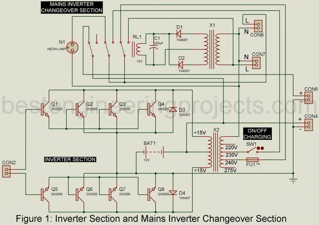
Inverter section | Offline UPS Circuit
The inverter portion has transformer X2 as its chief component surrounded by NPN power transistors 2N3055 (T1 through T8) and power diodes 1N5407 (D3-D4). Almost eight Transistors are arranged in two banks. We can place as many transistors as required on each bank for a specific VA rating of the device. This circuit has been modeled to produce a 350VA capacity device and thus we use four transistors per bank. For the construction of 550VA, 650VA, and 1000VA rating devices, you should use five, six, and seven transistors in each bank of the circuit.
The transistors T1-T8 are fixed on the common heat sink. One must be careful not to touch base and emitter terminals of transistors with the heat sink. It is because the collector terminal of the transistor is made of metal and thus needs to be separated from the sink contact. A mica separator is used to avoid that situation.
Observing fig.1 you can establish the connection between each component of the circuit; transistor terminals, transformer X2, diodes D3-D4, battery-status-indicator section, and oscillator section. There also shouldn’t be any form of contact between the heat sink and the UPS box.
Battery Status Indicator Section | Offline UPS Circuit
The status of batteries also needs to be monitored constantly, This section does the job. The level monitoring circuit is fixed to the battery through connectors CON3-CON4 combination. Check the polarity properly while making connections with the 12V battery. Potentiometer VR3 is used to set the overcharge status of 14.4V and LED2 is used to indicate that situation.
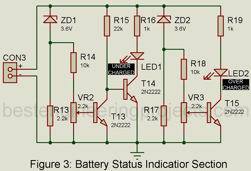
Turning the switch SW1 off helps to protect the battery from overheating. If LED is off the normal charging of the battery is ensured. The diode rectifier circuit made of D3 and D4 won’t work when the switch SW1 is in an off state and it prevents the battery from further charging and reaching overcharged state. The charging of the battery continues as it hits the least preset level of 11.3V asset in the circuit and LED1 glows to verify the low-level status.
To restart the charging process of the battery, switch SW1 needs to be closed. The circuit cannot work in absence of AC mains and battery voltage below the preset limit of 11.3V and so all the loads must be disconnected instantly.
For more detail, about the Battery status indicator circuit, you can visit the given link: Battery Status Indicator Circuit
Oscillator section | Offline UPS Circuit
This circuit only operates when the AC mains supply is absent. This duplicate mains supply generates a low-level AC voltage (15V-0-15V) working together with the transistor banks; T1-T8. The output is supplied through the transformer X2 after stepping up the voltage.
It is constructed using NE555 timer (IC2), dual JK flip-flop 4027 (IC1), transistors SK100 (T11-T12), and BC547 (T9-T10), voltage regulator 7805 (IC3), and some discrete components. Out of all components, NE555 is the chief component that is modeled in astable multivibrator mode.
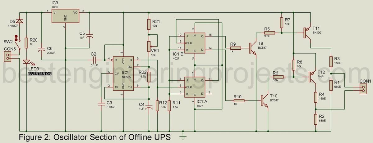
The preset VR1 is used to fix the timer frequency at 200Hz and this produces a 50Hz line frequency at CON1. The pin3 (CP2) of the second flip-flop of the IC1 receives clock-pulse input from pin 3. The first flip-flop is clocked by this pin1 (Q2) output of the flip-flop. The flip-flops output Q1 and Q2 are fed to the base terminals of transistors T9 and T10, respectively. The outputs are amplified to 2.2V by the transistors T11 and T12 and again fed to the base terminals of transistors T4 and T8, they amplify the input voltages to12V. Connectors CON1 and CON2 establish the connection between the oscillator and the two transistor banks.
A 7805 voltage regulator supplies the 5V DC power required for the circuit. After connecting connectors CON5 to CON6, we get output voltage from the battery and it is then fed to the regulator through relay RL1 and a switch. When the switch S2 is closed, the battery voltage makes its way into the regulator through pin 9 and pin 3 of RL1 to pin 1 of the regulator circuit. Under normal condition, when the AC mains run through the circuit, the relay is activated, and pin 9 and pin 3 of RL1 gets disconnected. The supply to the oscillator is cut off and it results in the turning off of the inverter circuit.
The Relay RL1 of the circuit is the controller section. It determines the alteration in between the choice of supply required for the devices. RL1 is a 12V, three contacts changeover (three-poles double-throw) relay. Its connection to the circuit is shown in fig. 1.
Working on the Offline UPS Circuit
The UPS circuit operates under two different cases:
- Presence of AC mains supply
- Absence of AC mains supply
When AC mains Supply is Available
This is the normal mode. Under this condition, transformer X1 receives 230V AC input mains supply. It energizes the Relay RL1 and terminals 7, 8, and 9 of the relay come into contact with terminals 4, 5, and 6, respectively. The Phase of the AC mains supply gets connected to terminals 4, 7, 5, and 8 of the relay and the output socket where we connect the load. Hence, the AC mains are supplied at the output terminal of the UPS circuit through CON8.
As soon as we close the switch SW1, the phase of the input mains gets connected to 230V tapping of transformer X2 through terminal 5 which is in contact with terminal 8 of the relay. Transformer X2 acts as a step-down transformer for the neutral connection is common. This 230V AC supply gets stepped down to 15V-0-15V AC and a full-wave rectifier diode combination (diodes D3-D4) rectifies this value to DC voltage. The transformer X2 has a capacitor C7 connected across its center tap. A current limiter (4.7-ohm, 20W resistor) is better to be used in series with a positive terminal of the battery for better working. This value is to be set as per the requirement of the circuit.
Thus generated DC supply charges the battery and terminal 9 of the relay gets connected with terminal 6 and that is when the power supply is interrupted to the oscillator circuit and deactivates the inverter circuit. By then, the battery is fully charged switch SW1 should be open and LED2 starts to glow
When AC mains supply is not Available
As the mains is interrupted, transformer X1 doesn’t work, and relay RL1 is not energized. Thus, terminals 7, 8, and 9 of the relay establish contact with terminals 1, 2, and 3, respectively. And, terminal 9 connected to the positive terminal of the battery makes its way to the oscillator circuit. It triggers the inverter circuit.
Transformer X2 is connected to terminal 1 of the relay RL1 and thus 240V AC voltage from X2 is passed to the relay. Terminals 7 and 8 are in contact with terminals 1 and 2 of the relay and so 240V AC is supplied to the output terminal CON8. When the load is directly connected to the UPS, there are chances of voltage drop and so to prevent this we connect the output to 240V tapping. There is a Neon lamp in between terminal2 and neutral. When the UPS is turned on, the lamp glows.
More Inverted and UPS circuit posted in bestengineeringprojects.com
- 3000W Inverter with Inbuilt Charger using AT89C2051
- Crystal controlled inverter | Verified Inverter Circuit
- Advance Mini UPS
PARTS LIST OF OFFLINE UPS CIRCUIT
| Resistors (all ¼-watt, ± 5% Carbon) |
| R1, R2 = 680Ω
R3, R4 = 150Ω, 2W R5, R6, R12 = 3.3 KΩ R7, R8, R14, R18, R21 = 10 KΩ R9, R10, R16, R19, R20 = 1 KΩ R11= 1.5 KΩ R13, R17 = 2.2 KΩ R15 = 22 KΩ R22 = 4.7 KΩ VR1 = 10 KΩ preset VR2, VR3 = 2.2 KΩ preset |
| Capacitors |
| C1, C6 = 220 µF, 25V (Electrolytic capacitor)
C2 = 0.1 µF (Ceramic Disc) C3 = 0.01 µF (Ceramic Disc) C4, C5 = 1 µF, 25V (Electrolytic capacitor) C7 = 330 µF, 35V (Electrolytic capacitor) |
| Semiconductors |
| IC1 = 4027 (Dual JK Flip-Flop)
IC2 = NE555 (Timer IC) IC3 = 7805 (5V Series Voltage Regulator) T1 – T8 = 2N3055 (NPN Power Transistor) T9, T10 = BC547 (NPN Transistor) T11, T12 = SK100 (PNP Transistor) T13 – T15 = 2N2222 (NPN Transistor) D1, D2, D5 = 1N4007 (Rectifier Diode) D3, D4 = 1N5407 (Rectifier Diode) LED1 – LED3 = 5mm Any Color LED ZD1, ZD2 = 3.6V Zener Diode |
| Miscellaneous |
| X1 = 230V AC Primary to 12V-0-12V, 500mA Secondary Transformer
X2 = 15V-0-15V Secondary and 350VA Inverter Primary Transformer SW1, SW2 = ON/OFF Switch RL1 = 12V, 3C/O Relay with 6A Contact Rating N1 = 230V AC Neon Lamp F1 = 1A Fuse CON1 – CON7 = 2-Pin Connector CON8 = 6A, 3-pin Output Socket LED Holder (Three) BATT1 = 12V, 7Ah Battery |
Mini offline ups project all details file
I really like it. please let me know when there’s anything shared