Here is a simple circuit using transistor called ‘Battery Status Indicator Circuit’ used to indicate two states of battery i.e. under charged and over charged. Previously, we had already posted similar circuit called Battery Voltage State Indicator using 741 used to indicate three states of battery i.e. charged, charging and discharge. Similarly, you can also design circuit which indicate status of battery in 10 different level.
Circuit Description of Battery Status Indicator
The circuit of Battery Status Indicator Capacitor is shown in figure 1. The main components of Battery State Indicator circuit are three low power general purpose transistor 2N2222.
The status of batteries also needs to be monitored constantly, This, circuit does the job. The level monitoring circuit is fixed to the battery as shown in circuit. Check the polarity properly while making connections with the 12V battery.
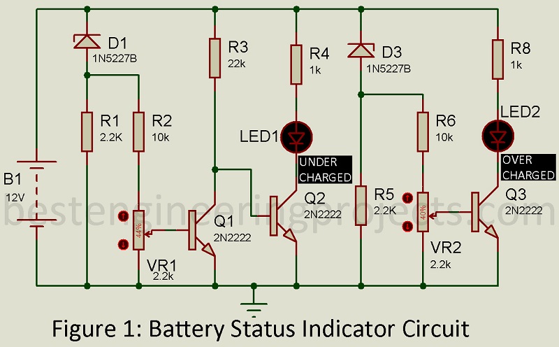
The zener diode connected in the circuit is in reverse mode in order to produce regulated output of 3.6V. Potentiometer VR1 is used to adjust the lower voltage of battery. When battery voltage reaches lower then predetermined value LED1 start to glow. Thus, LED1 is used to indicate under charge voltage situation. Similarly, VR2 is used to adjust the higher voltage of battery. When battery voltage reaches higher then predetermined value LED2 start to glow. Thus, LED2 is used to indicate over charge voltage situation.
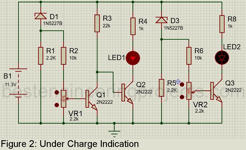
Turning the switch off helps to protect the battery from overheating. If LED is off the normal charging of the battery is ensured. The charge of the battery continues as it hits the least preset level of 11.3V as set in the circuit and LED1 glows to verify the low-level status.
Calibration of Battery State Indicator:
Wire up the entire circuit component as shown in circuit diagram. For under charge voltage calibration connect the variable DC power supply in place of battery and set voltage to 11.3V. Adjust potentiometer till LED1 start to glow.
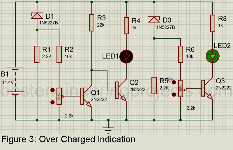
For over charged voltage calibration connect the variable DC power supply in place of battery and set voltage to 14.4V. Adjust the potentiometer till LED2 start to glow.
PARTS LIST
| Resistors (all ¼-watt, ± 5% Carbon) |
| R1, R5 = 2.2 KΩ
R2, R6 = 10 KΩ R3 = 22 KΩ R4, R7 = 1 KΩ VR1, VR2 = 2.2 KΩ |
| Semiconductors |
| Q1 – Q3 = 2N2222 (General Purpose NPN bipolar junction transistor)
D1, D2 = 1N5227B (3.6V zener diode) LED1 = 5mm Red Color LED LED2 = 5mm Green Color LED |
| Miscellaneous |
| BAT1 = Battery to Monitor |
that’s is all about